OV-C2-AG-06-BSTACK · v0.1 · 2026-08-15Download PDF
Doctype
Assembly Guide
Doc id
OV-C2-AG-06-BSTACK
Product line
openvvvf
Applies to
chassis-size-2
Version
0.1
Date
2026-08-15
Description
Assemble the bottom stack onto the Chassis Size 2 heatspreader, including spacers, DC-link bus bars, filter board, and phase bus bars.
Nav order
229
Normative refs
OV-C2-IG-INDEX
Bottom Stack Assembly
This guide covers installing the bottom spacers, DC-link bus bars, DC-link filter board, and phase bus bars onto the Chassis Size 2 heatspreader. At the end of this stage the assembly is still loose and must be handled carefully until the remaining hardware is bolted down in later steps.
Safety
- Do not power the inverter until all assembly, torque, and inspection steps are complete.
- Keep the work area clean; stray screws, washers, or metal debris can short high-voltage bus bars.
- The assembly is not rigid after this step. Avoid moving it if possible; if you must move it, support it from underneath and do not lift it by the bus bars or filter board.
Warning: Gloves are mandatory for this step
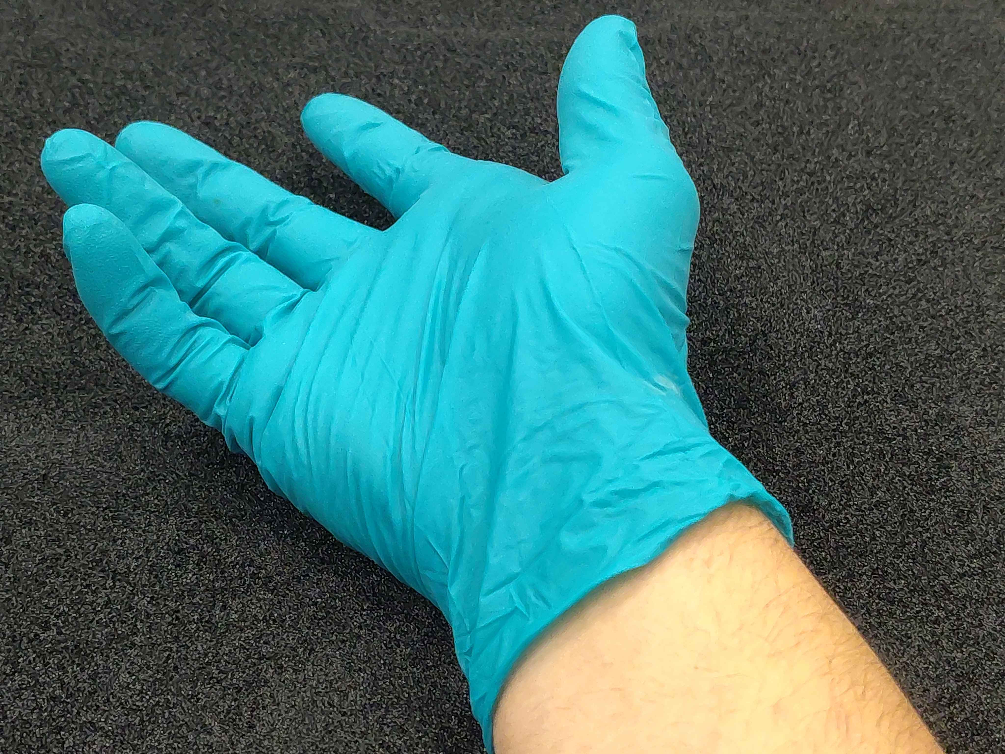
Wear clean gloves whenever handling bus bars, screws, or any high-current contact surface. Fingerprints and skin oils leave a thin film that increases electrical resistance at the joint. Higher resistance creates heat, and under load that heat can degrade the connection and lead to failure.
Wear clean gloves whenever handling bus bars to keep contact surfaces free of oils
Required materials and tools
Item
Qty
Notes
Heatspreader with mounted IGBT modules
1
From OV-C2-AG-02
Bottom spacers
6
13 mm OD × 63 mm aluminium standoff rods, M6 thread; stand-offs between baseplate and filter board (OV-C2-DD-DCLINK-THERMAL)
DC-link filter board
1
From OV-C2-AG-05-FILTER
DC-link bus bars
2
Positive and negative DC input
Phase bus bars
3
One per phase output
Phase bus-bar screws
3
Hand-tightened only for now
Thermal interface compound
as needed
For top and bottom of spacers
Clean gloves
1 pair
For handling bus bars
Hex key or driver
1
For the phase bus-bar screws
Lint-free wipes
as needed
For paste and fingerprint cleanup
These spacers are the aluminium standoff rods analysed in OV-C2-DD-DCLINK-THERMAL: they form the capacitor bank's conduction heat path and are also the electrical connection between the filter board and the capacitor bank board, so they must be aluminium - never substitute steel. See OV-C2-DD-DCLINK-THERMAL for the stack cross-section and the heat-path analysis.
Before starting, a few notes on workspace setup and the photos below:
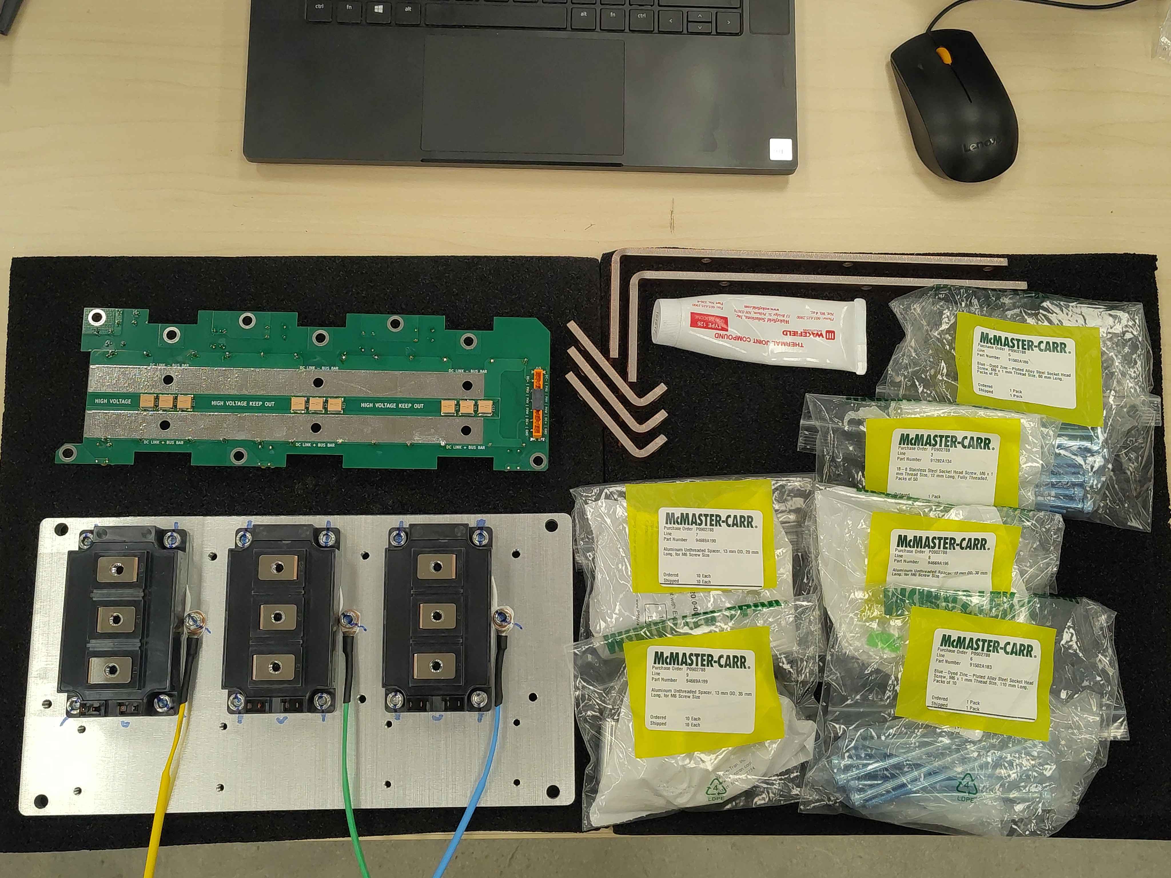
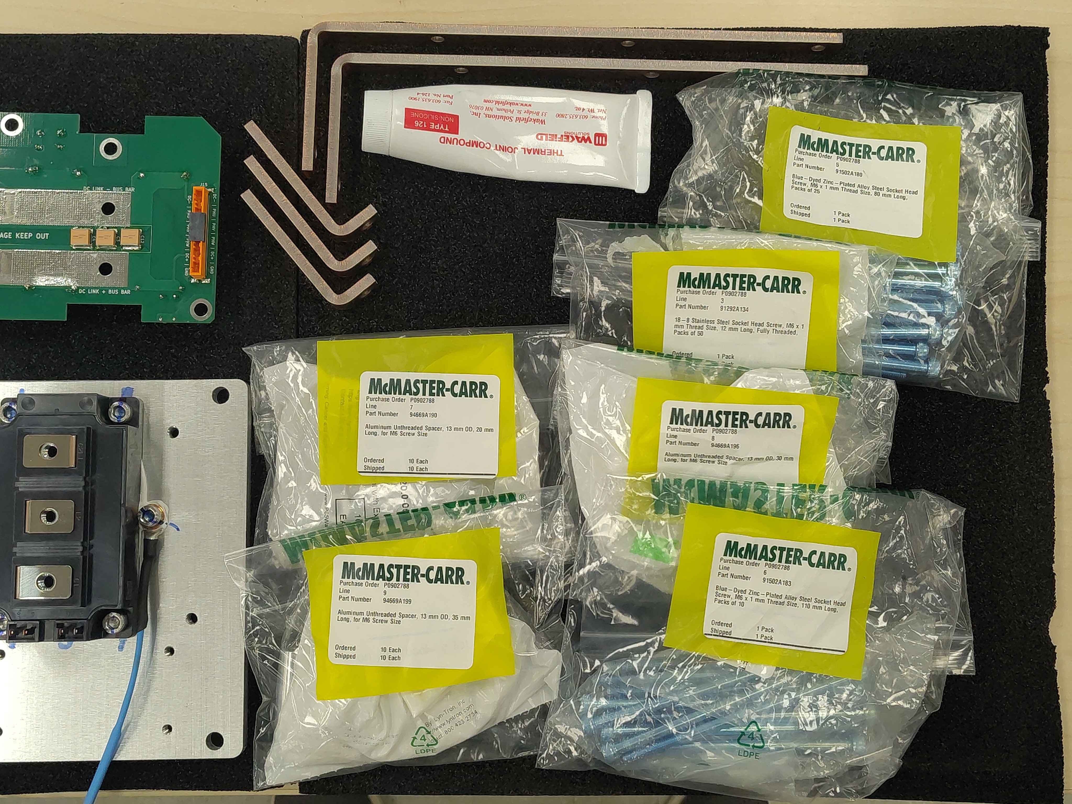
Errata: The workspace photos below show more parts on the bench than are actually used in this step. We started with extra hardware but cut the procedure short once the correct parts were identified; only the items listed above are needed here.
Tip: The black foam that Mouser ships around the Mitsubishi IGBT modules makes an excellent workspace mat for this step. It protects the heatspreader finish and the bus-bar surfaces from scratches.
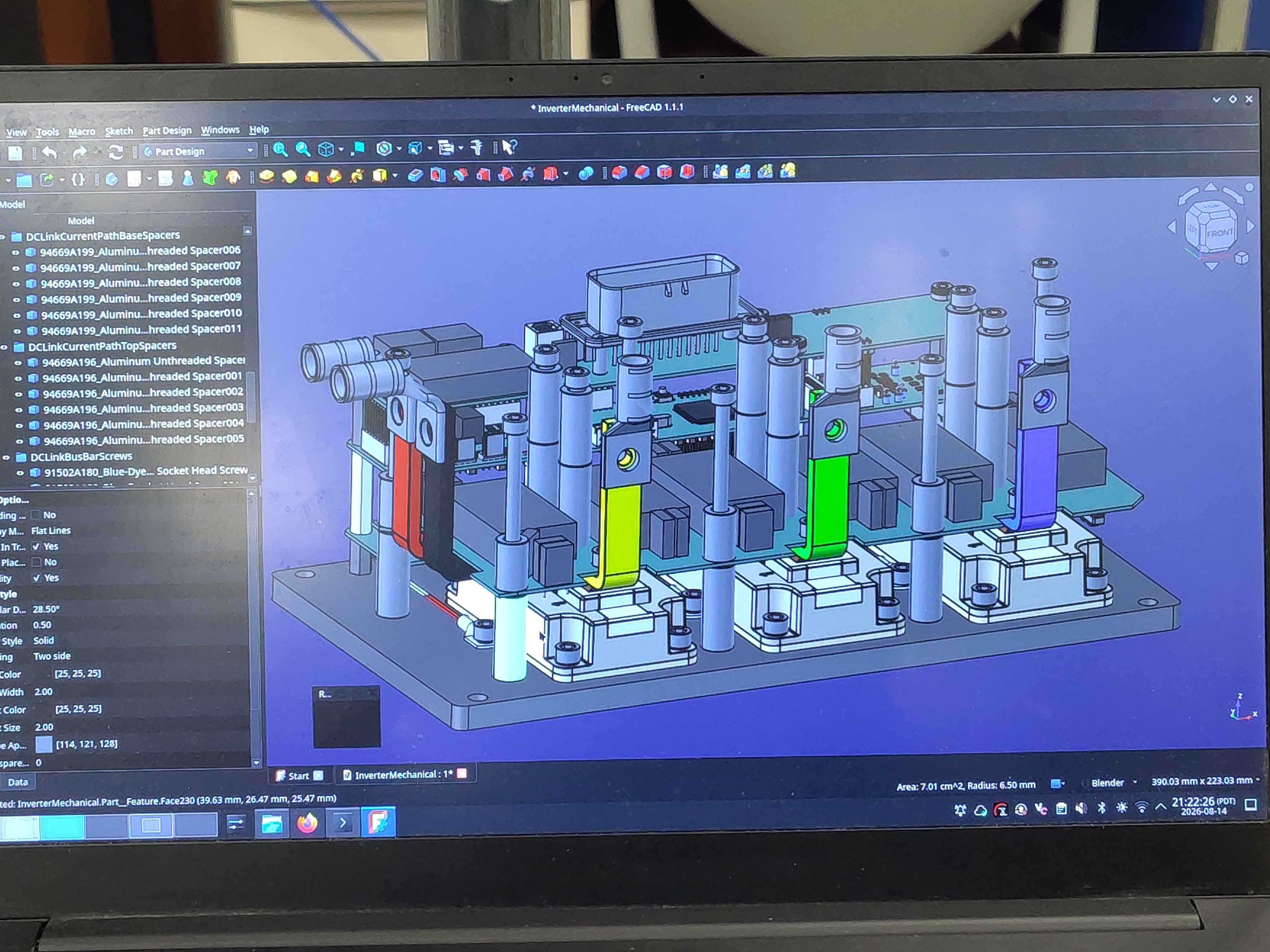
Tip: Have the CAD model open during this assembly. It makes it much easier to confirm the correct spacer locations, bus-bar orientation, and filter-board placement.
CAD model showing the spacer, bus-bar, and filter-board arrangement
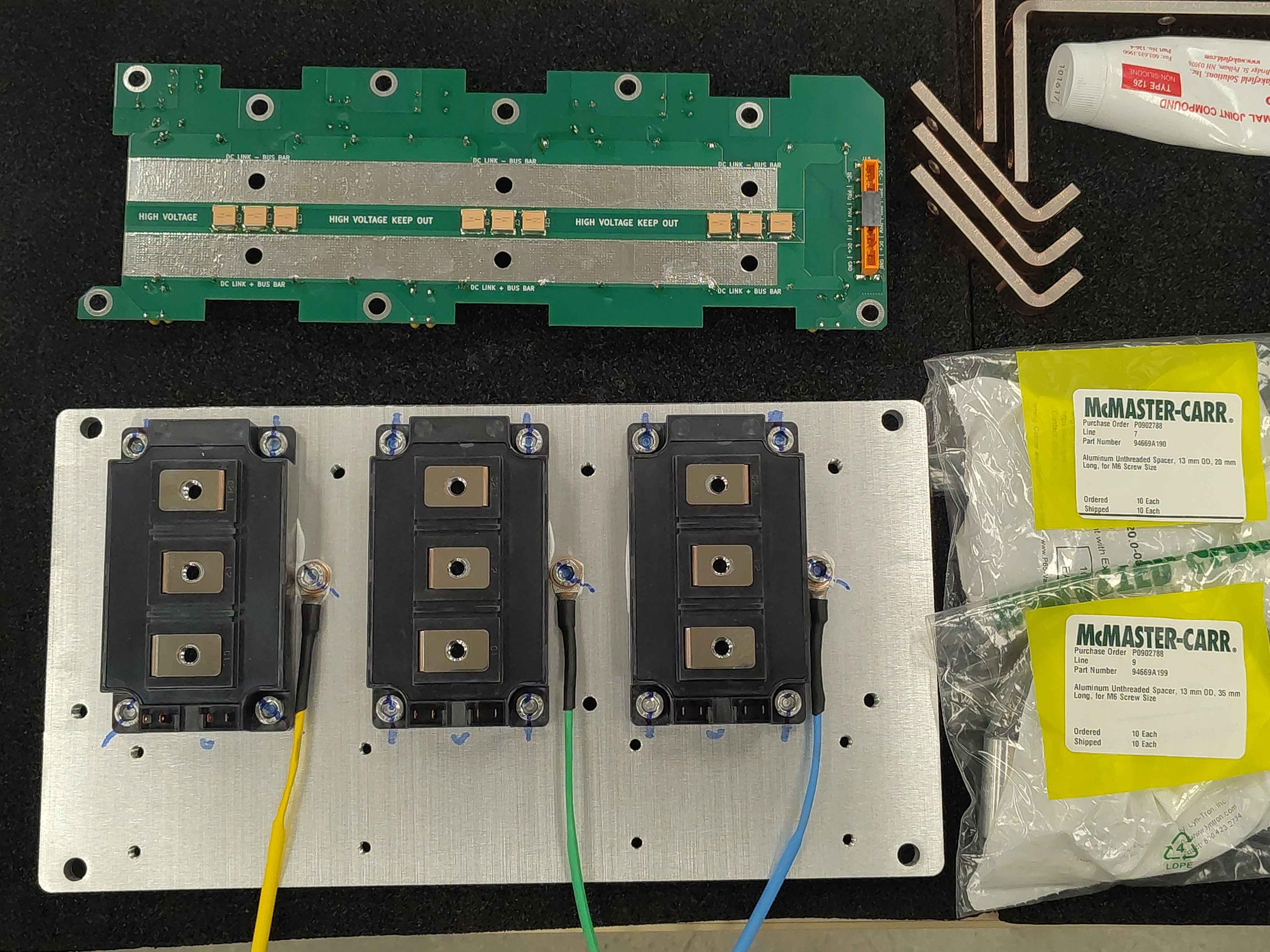
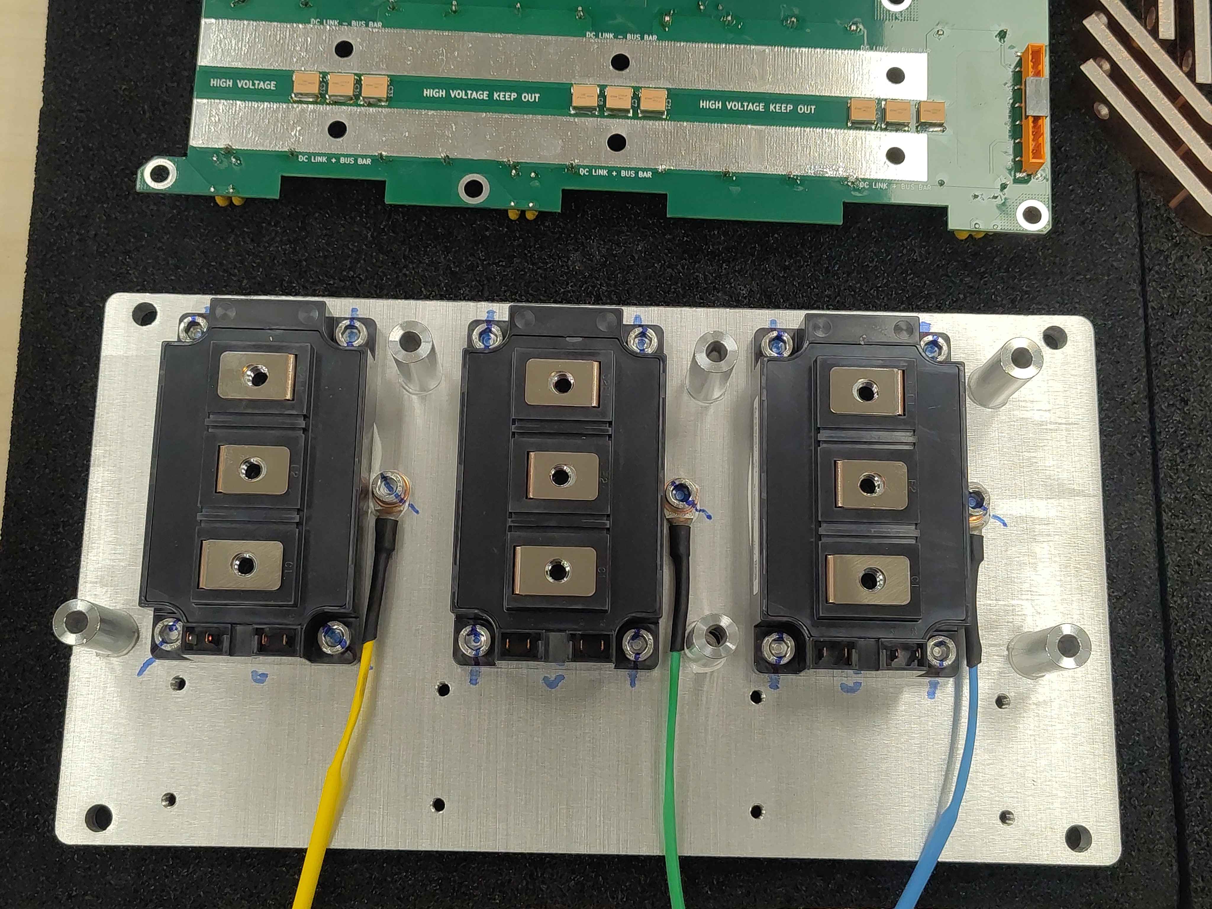
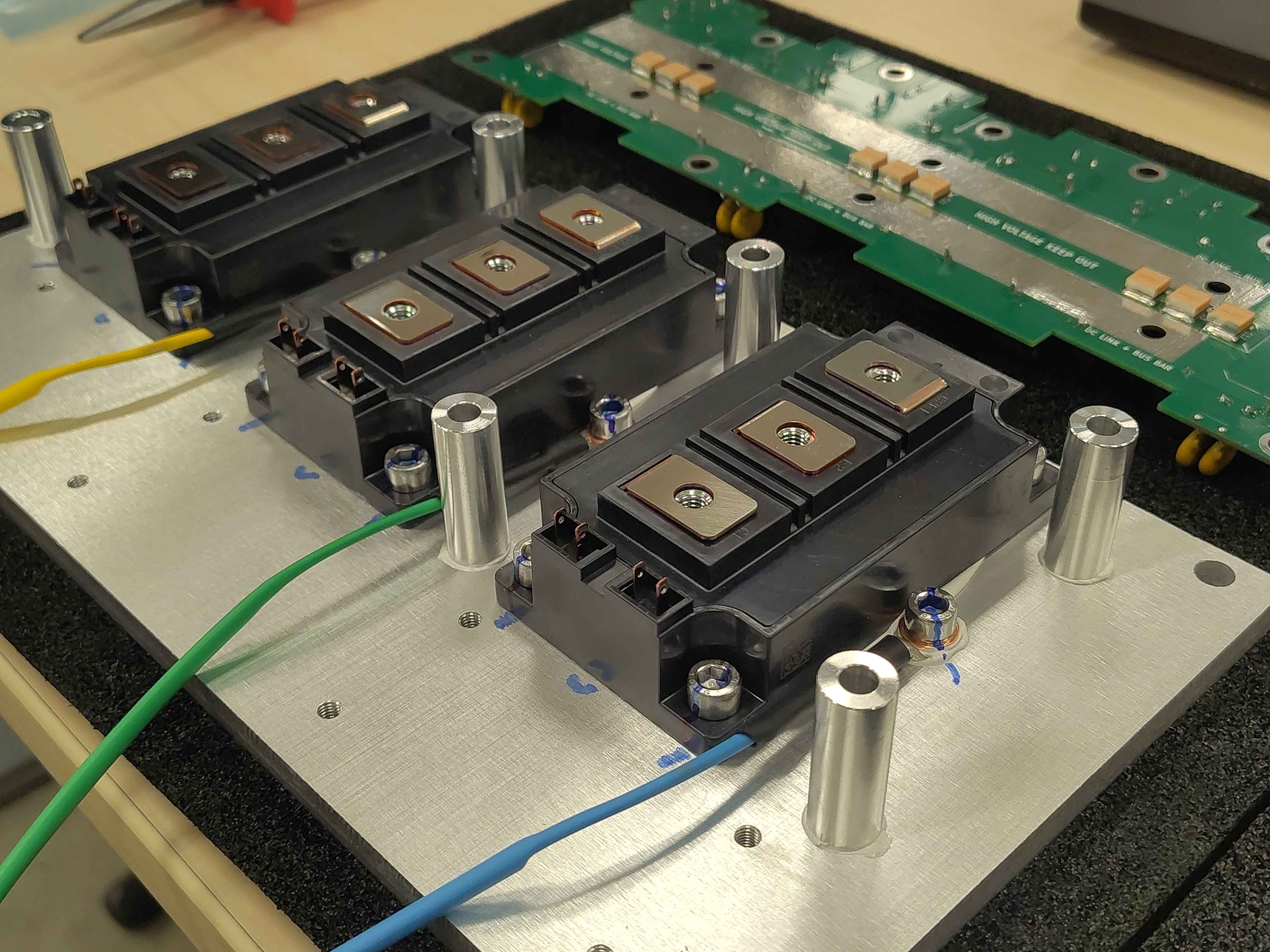
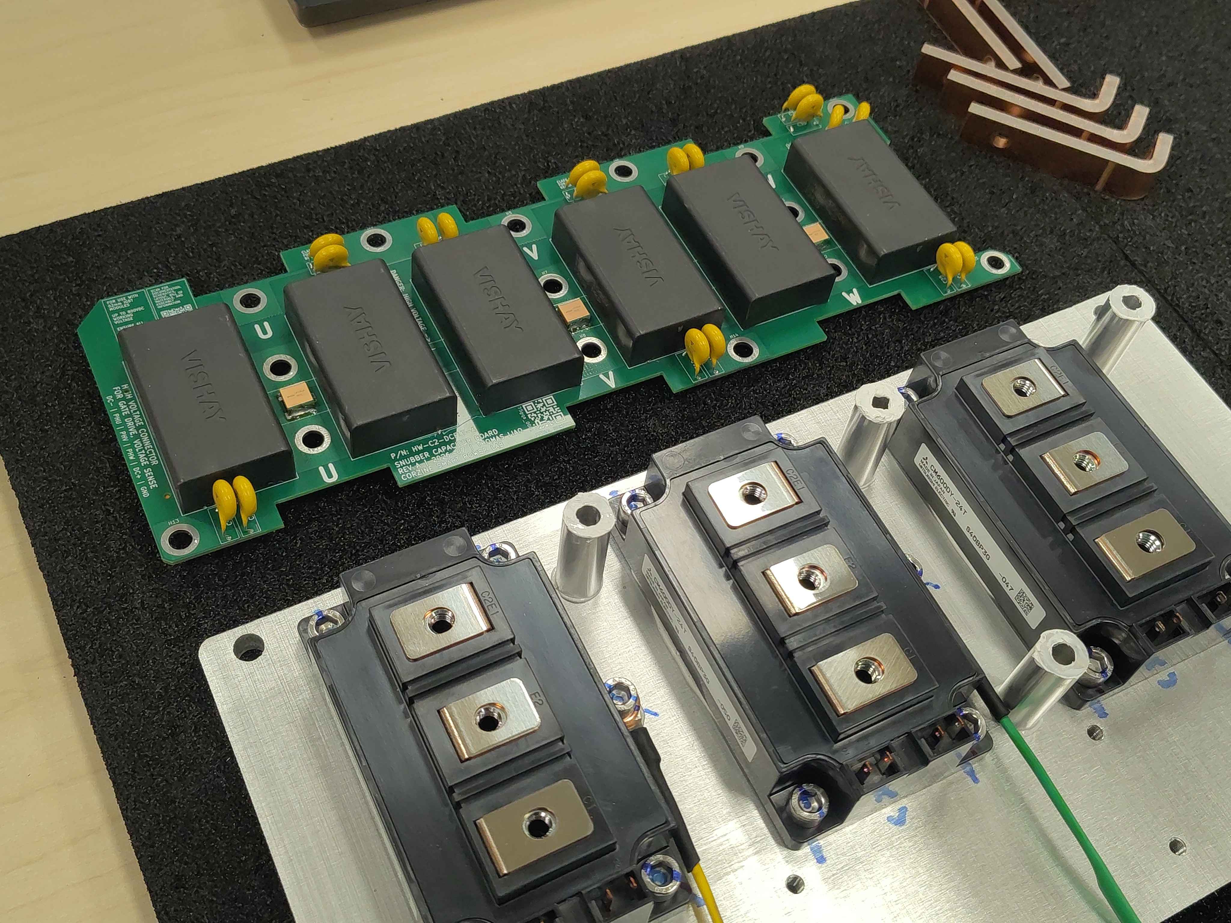
The photos below show the complete workspace laid out before assembly starts: the heatspreader with mounted IGBT modules, the six bottom spacers, the DC-link bus bars, the phase bus bars, and the DC-link filter board.
Overview of the workspace with heatspreader, spacers, bus bars, and filter boardFirst preparation view showing hardware laid outSecond preparation view showing hardware laid out
Step 1 - Paste and place the bottom spacers
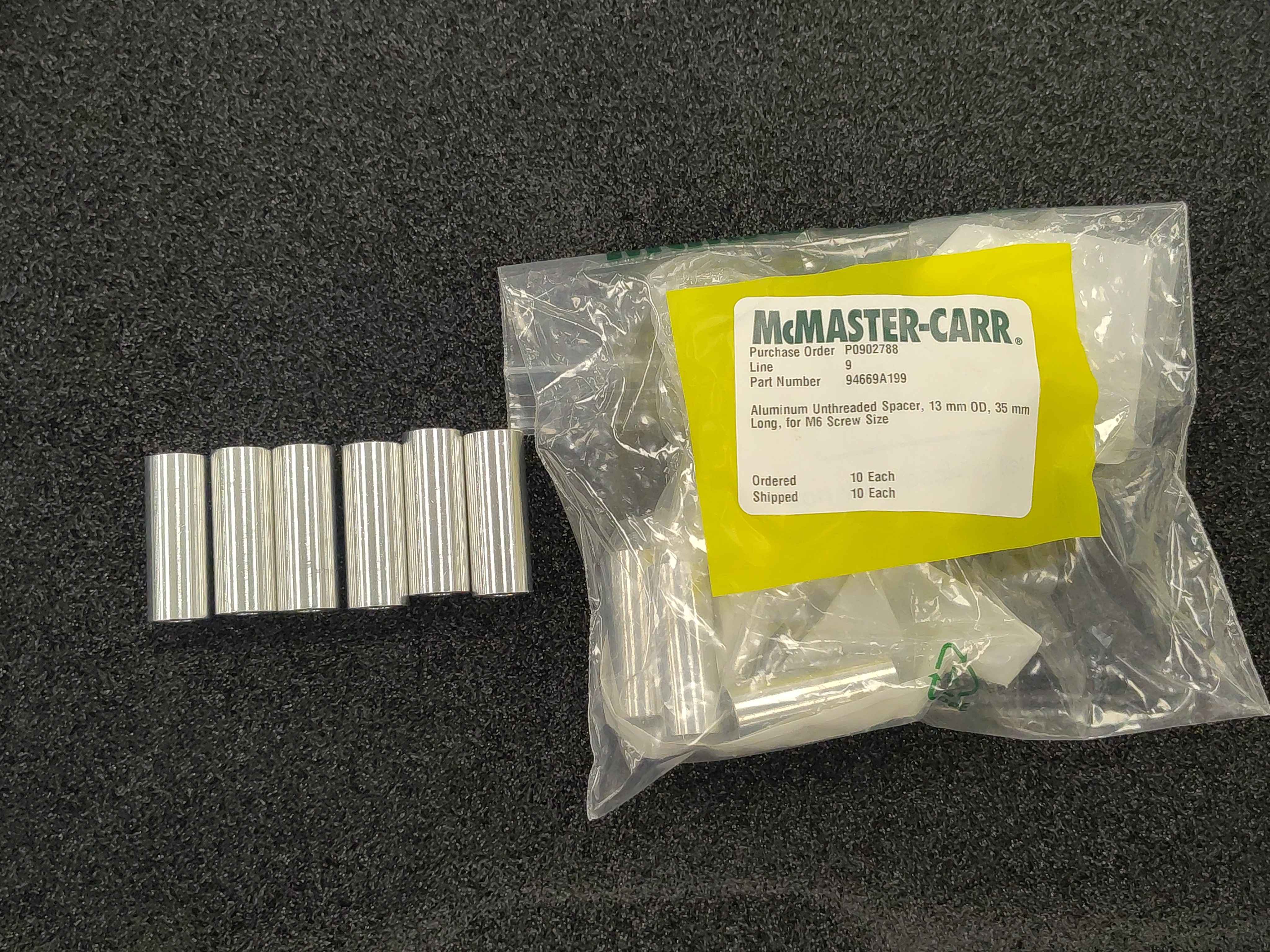
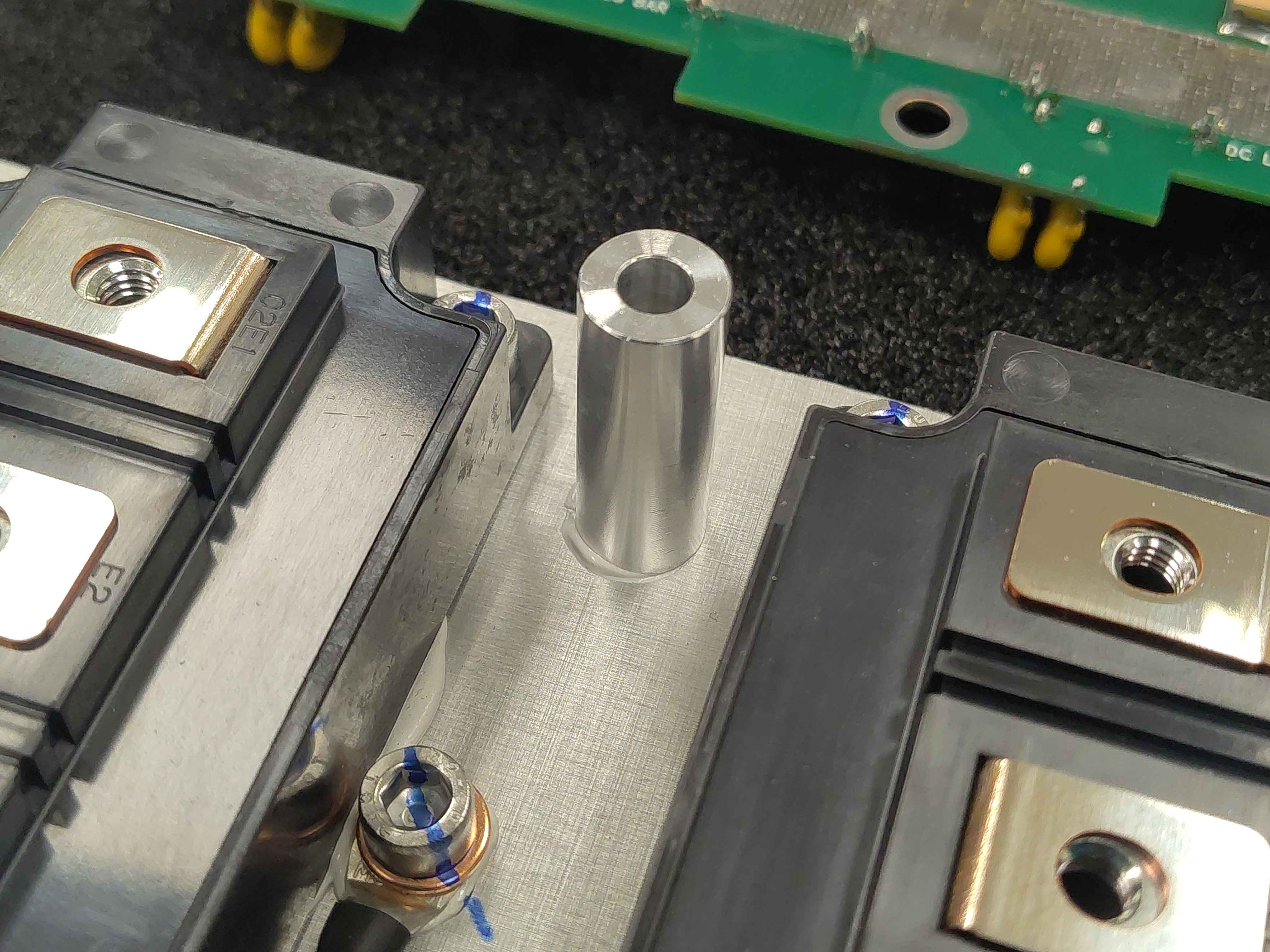
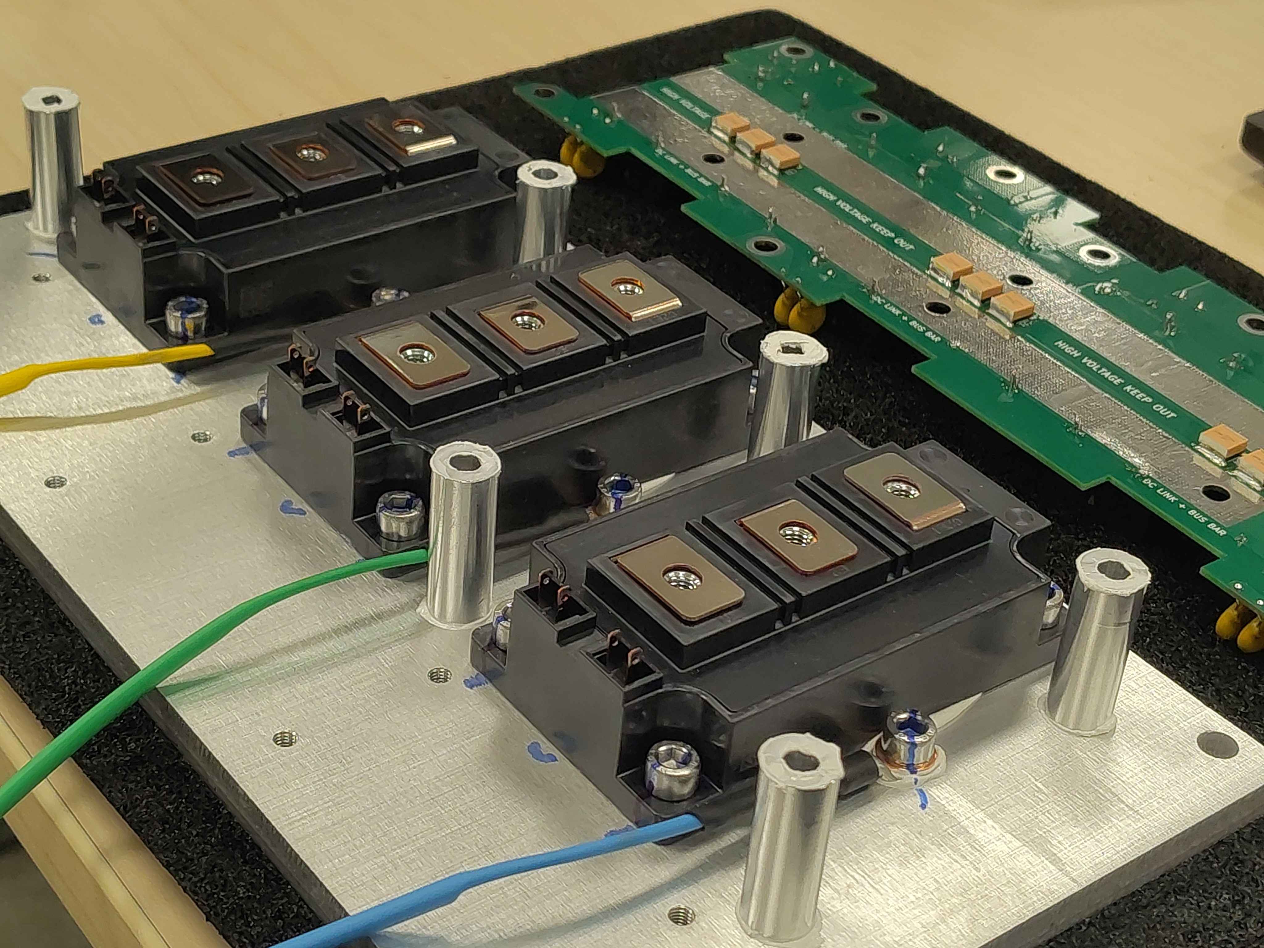
Lay out all six bottom spacers. Apply a thin, even layer of thermal interface compound to the bottom face of each spacer, then place the spacers onto the heatspreader in their intended locations. See the CAD model above or the all-spacers-placed photo below for the correct placement pattern.
All six bottom spacers laid out ready for assemblyThermal paste applied to the bottom of a spacerPlacing a pasted spacer onto the heatspreaderTop view of all six spacers placed on the heatspreaderAngled view of all six spacers placed on the heatspreader
Step 2 - Paste the tops of the spacers
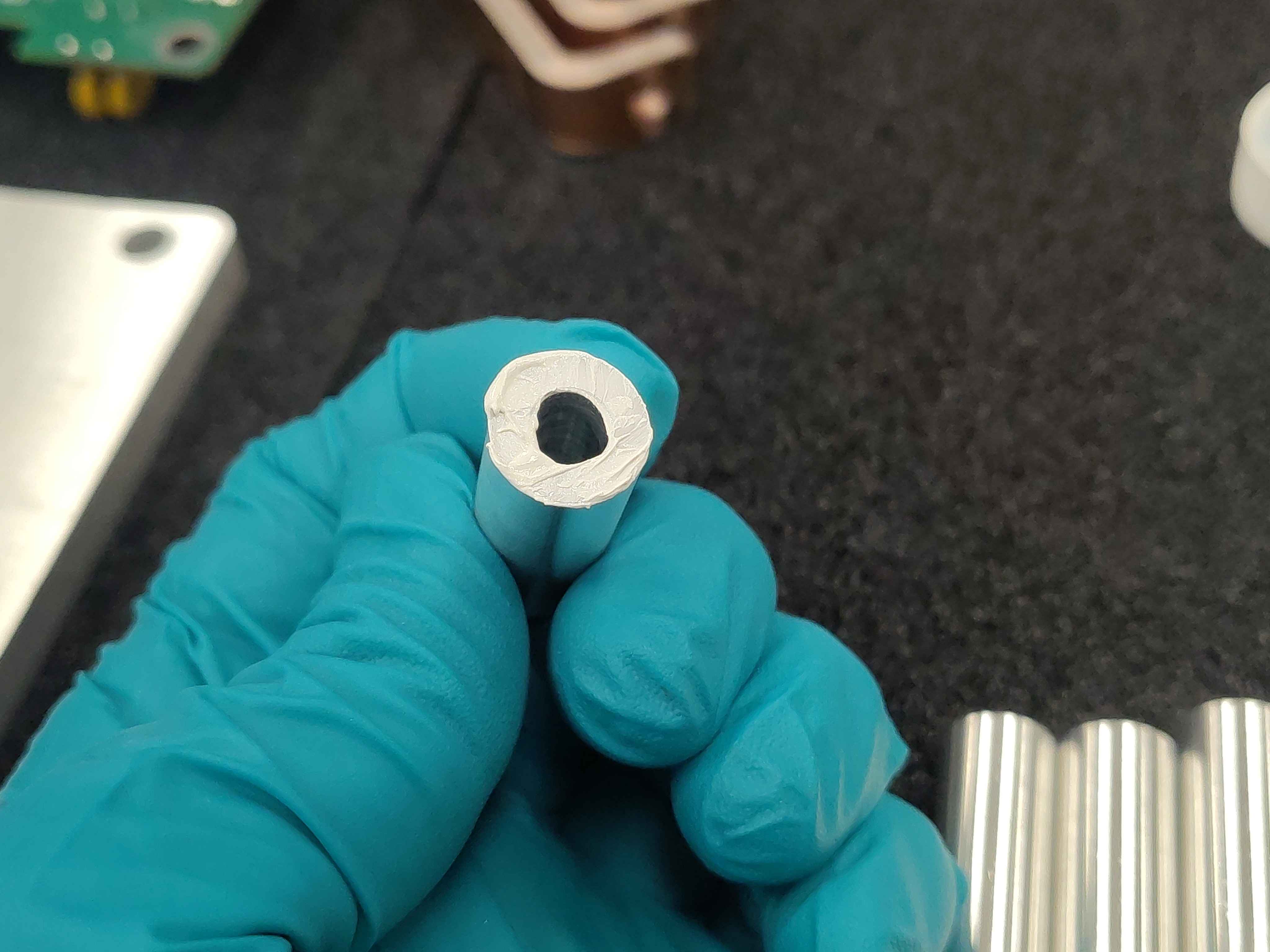
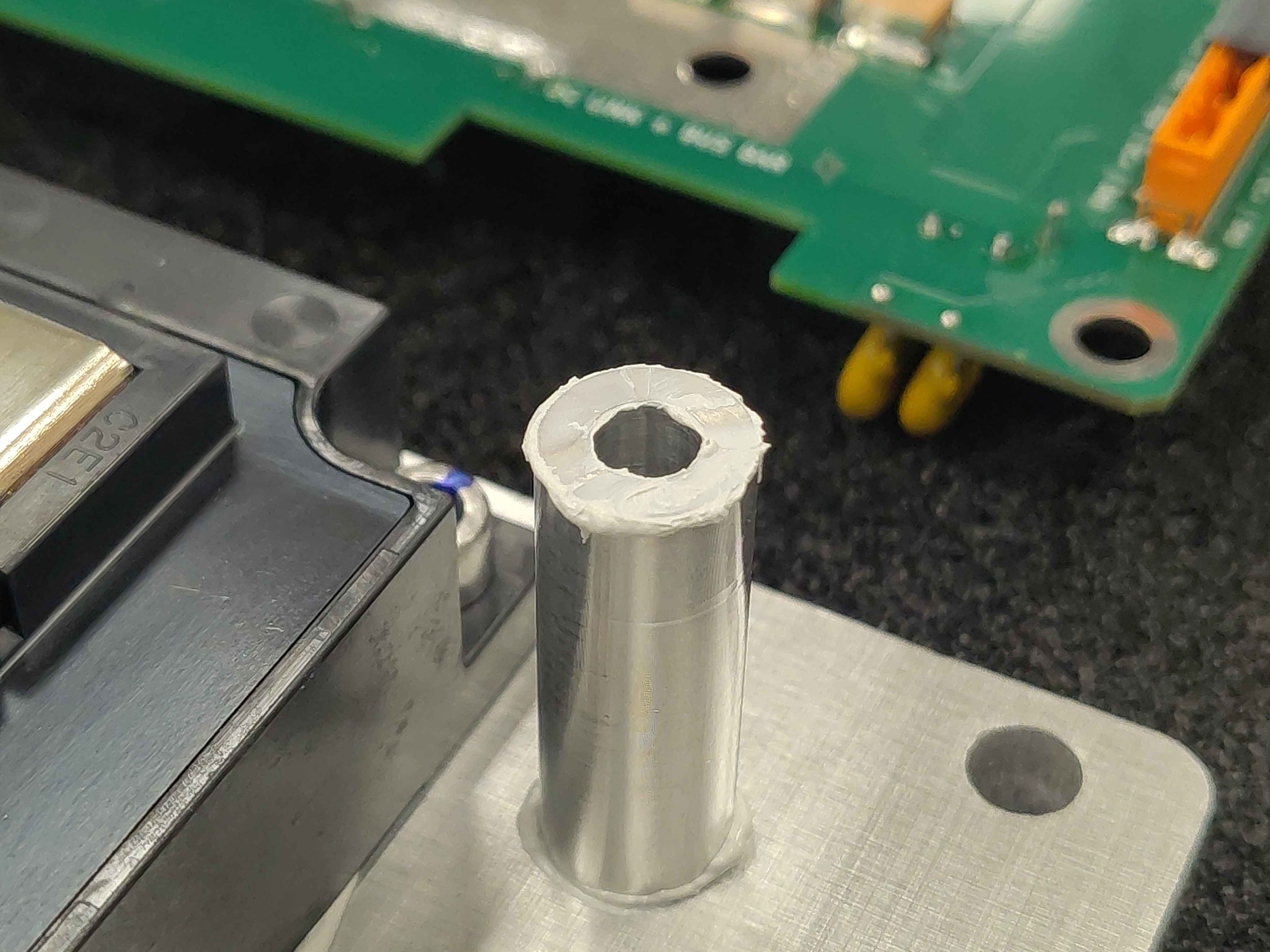
Apply thermal interface compound to the top face of each spacer. Spread it evenly so the filter board will sit flat and make good thermal contact.
Both faces of every rod are pasted because each rod end is a thermal contact in the capacitor bank's heat path: per OV-C2-DD-DCLINK-THERMAL, thermal paste at both interfaces roughly halves the contact-resistance temperature rise compared with dry metal-to-metal (6.6 °C vs 13.1 °C at the 40 W reference load).
Close-up of thermal paste on the top of a spacerAll spacers with paste applied to their top faces
Step 3 - Align the DC-link filter board
Hold the DC-link filter board above the assembly and confirm its orientation before lowering it. The connector and mounting holes must line up with the six spacers. Lowering the board twisted or offset will smear the thermal paste and can land on the wrong pads once the DC-link bus bars are added in the next step. Once the orientation is confirmed, set the board down on a clean, flat surface within easy reach - you will need both hands free for the bus-bar placement in Step 4.
Ensure the DC-link filter board is oriented correctly before placement
Step 4 - Set the DC-link bus bars on the IGBT modules
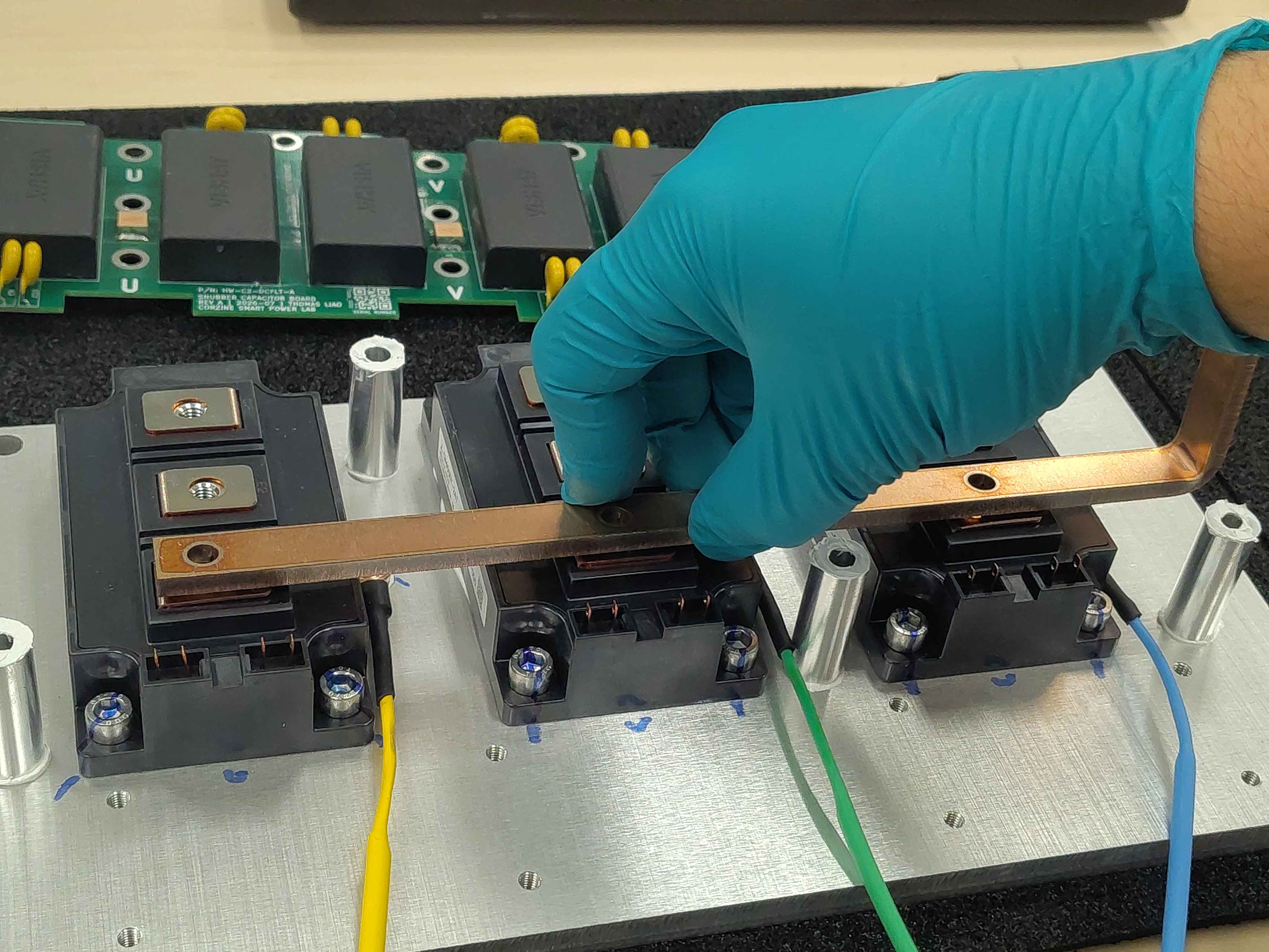
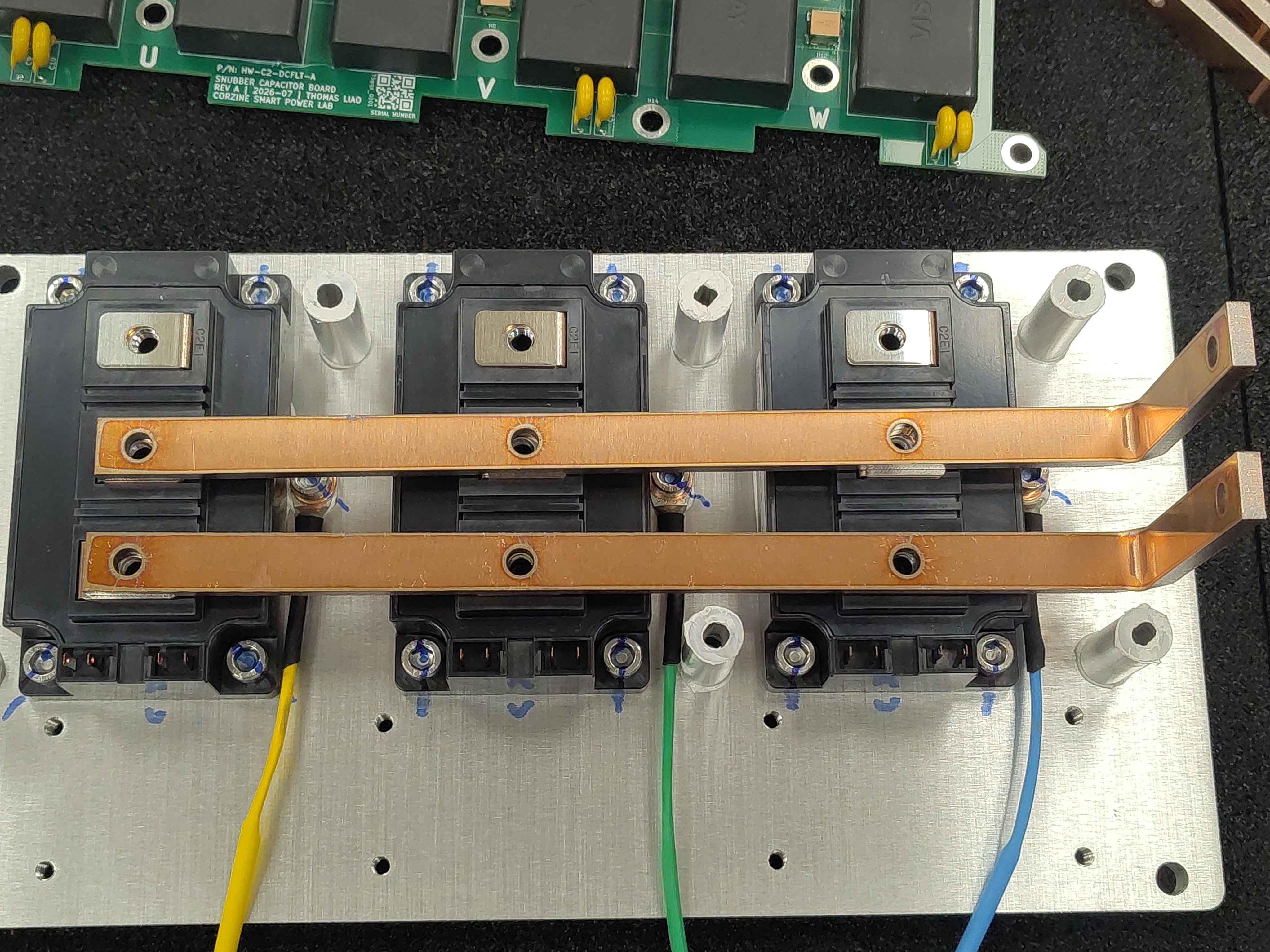
Lay the two DC-link bus bars across the tops of the IGBT modules. They are not fastened yet; they simply rest in position so the filter board can land on them.
Placing the DC-link bus bars onto the IGBT modulesBoth DC-link bus bars resting on the IGBT modules, viewed from above
Step 5 - Lower the DC-link filter board into place
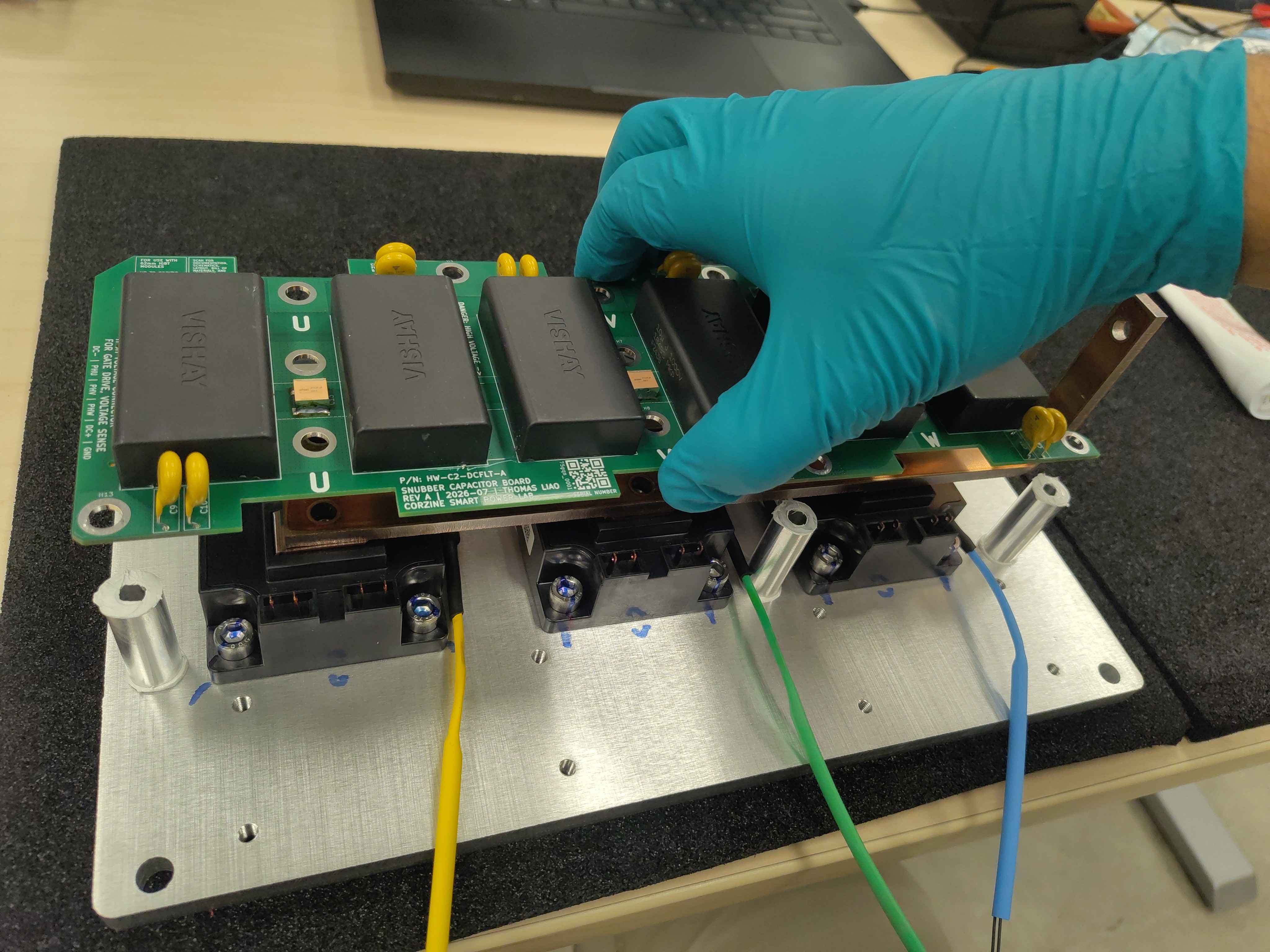
Carefully lower the DC-link filter board straight down onto the spacers and DC-link bus bars. Avoid sliding it sideways: any lateral movement will smear the thermal paste and can short the bus bars against the wrong pads.
Lowering the DC-link filter board onto the spacers and bus barsFilter board placed on the assemblyFilter board placed, alternate viewFilter board placed, second alternate viewFilter board placed, third alternate view
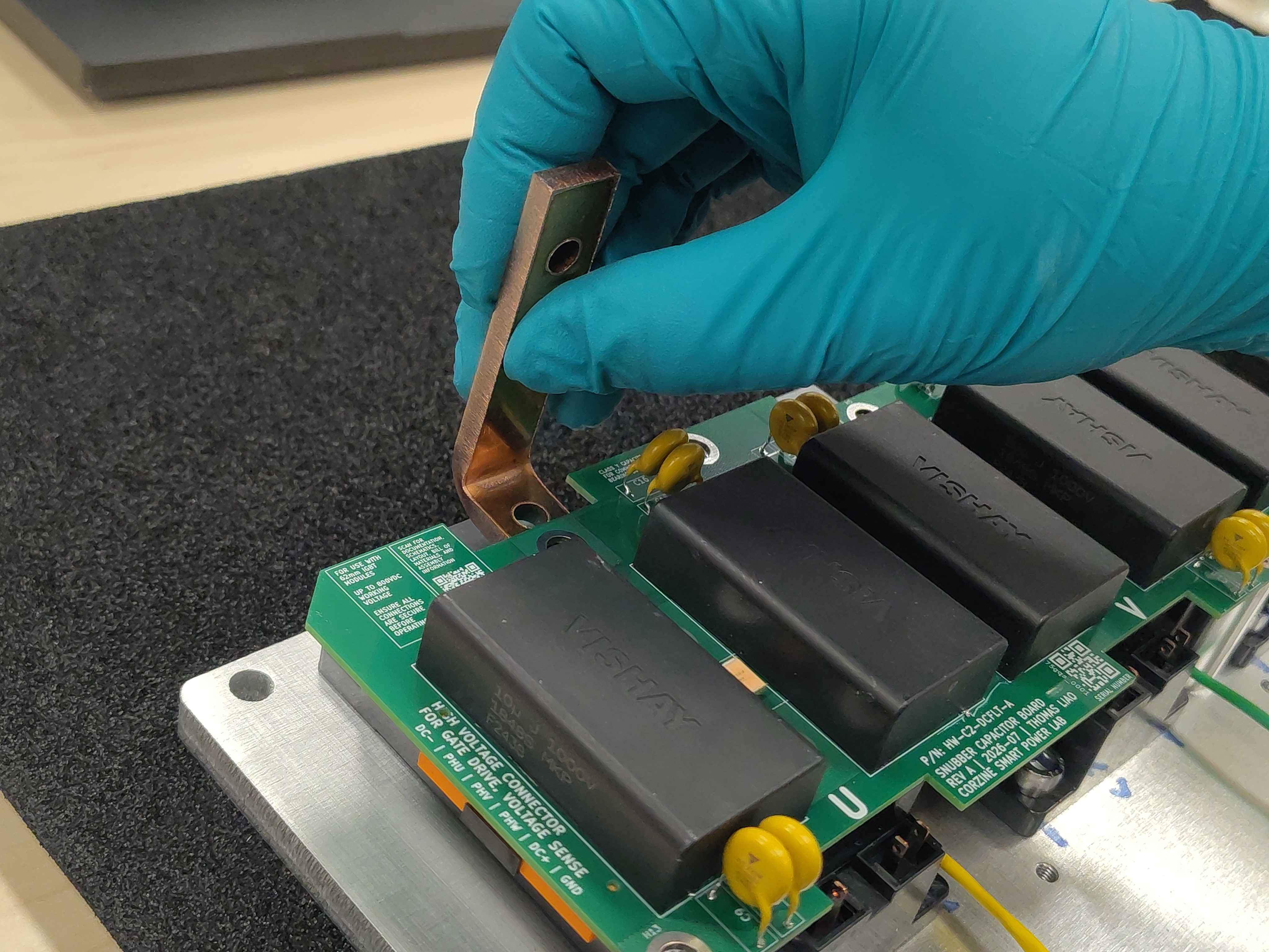
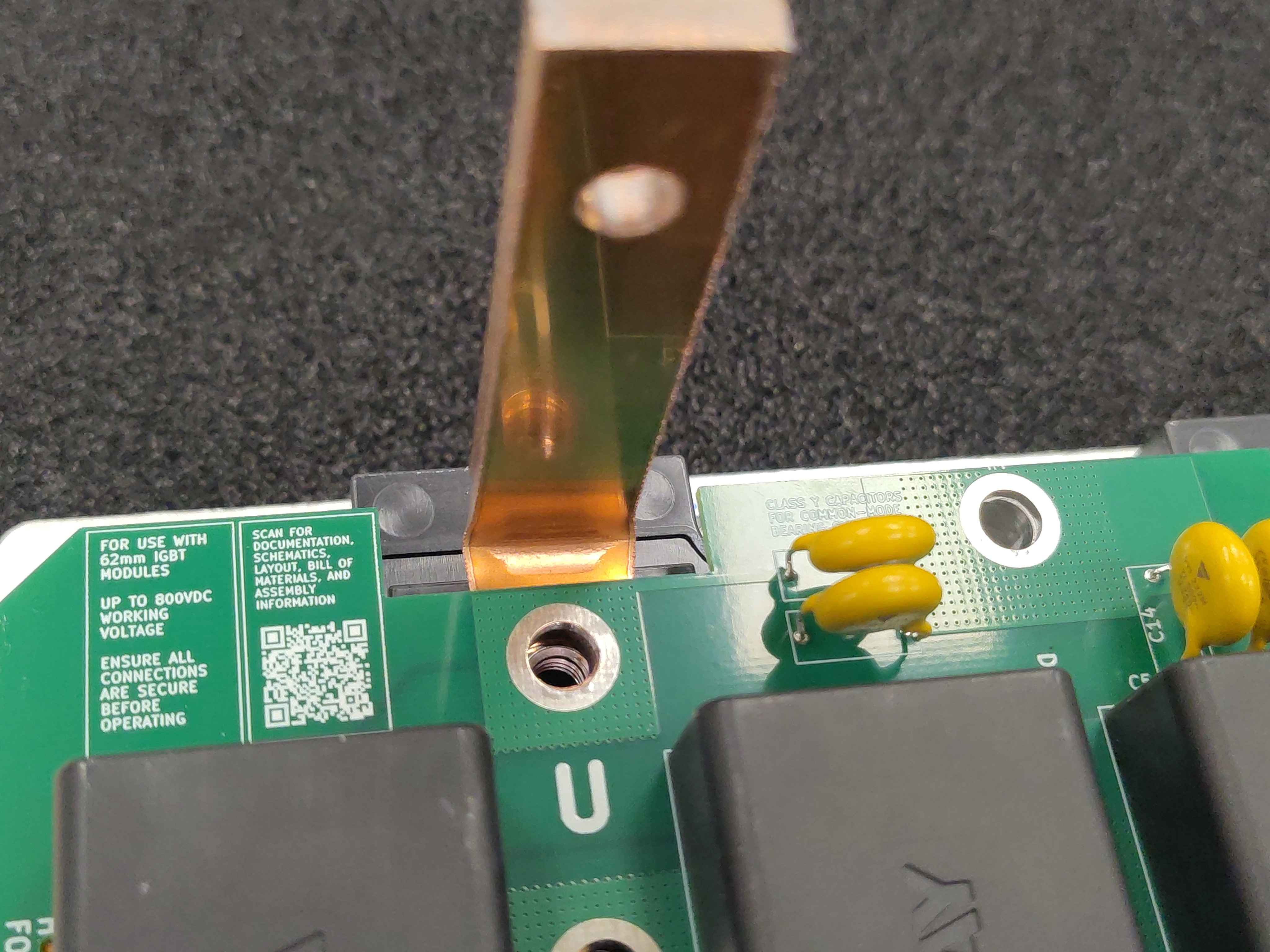
Step 6 - Insert the phase bus bars
Slide the three phase bus bars into place. The weight of the filter board will hold them in position while you work.
Tip: Insert the phase bus bars gently. They should slide under the filter board and rest on the IGBT module output terminals without forcing anything.
Carefully sliding a phase bus bar into positionClose-up of a phase bus bar lined up with its terminalAll three phase bus bars placedAll three phase bus bars placed, alternate view
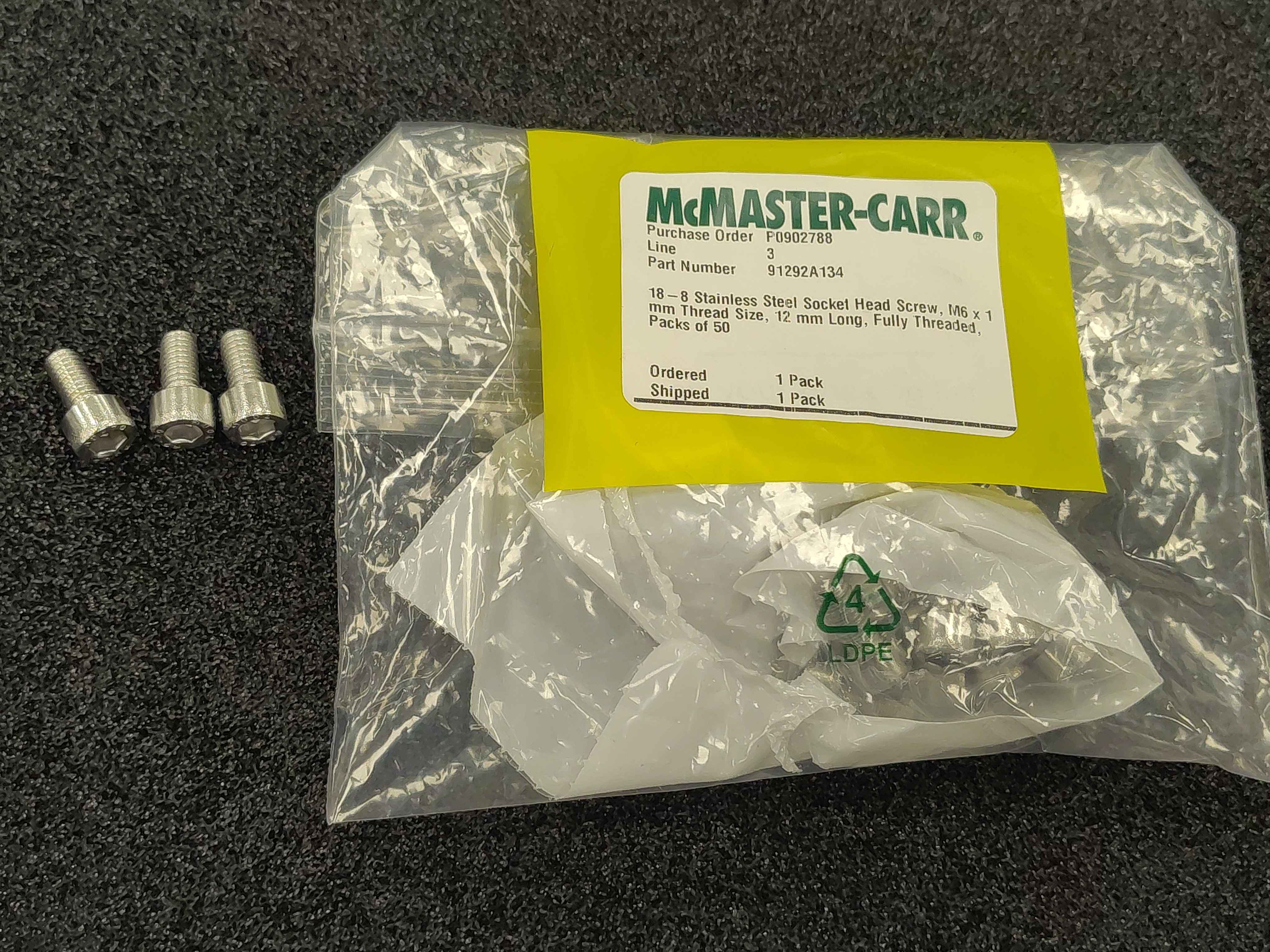
Step 7 - Prepare the phase bus-bar screws
Get the three phase bus-bar screws ready. Keep them clean and handle them with gloves; any oil transferred from your fingers to the screw or bus bar can end up on a high-current joint.
Phase bus-bar screws prepared for installation
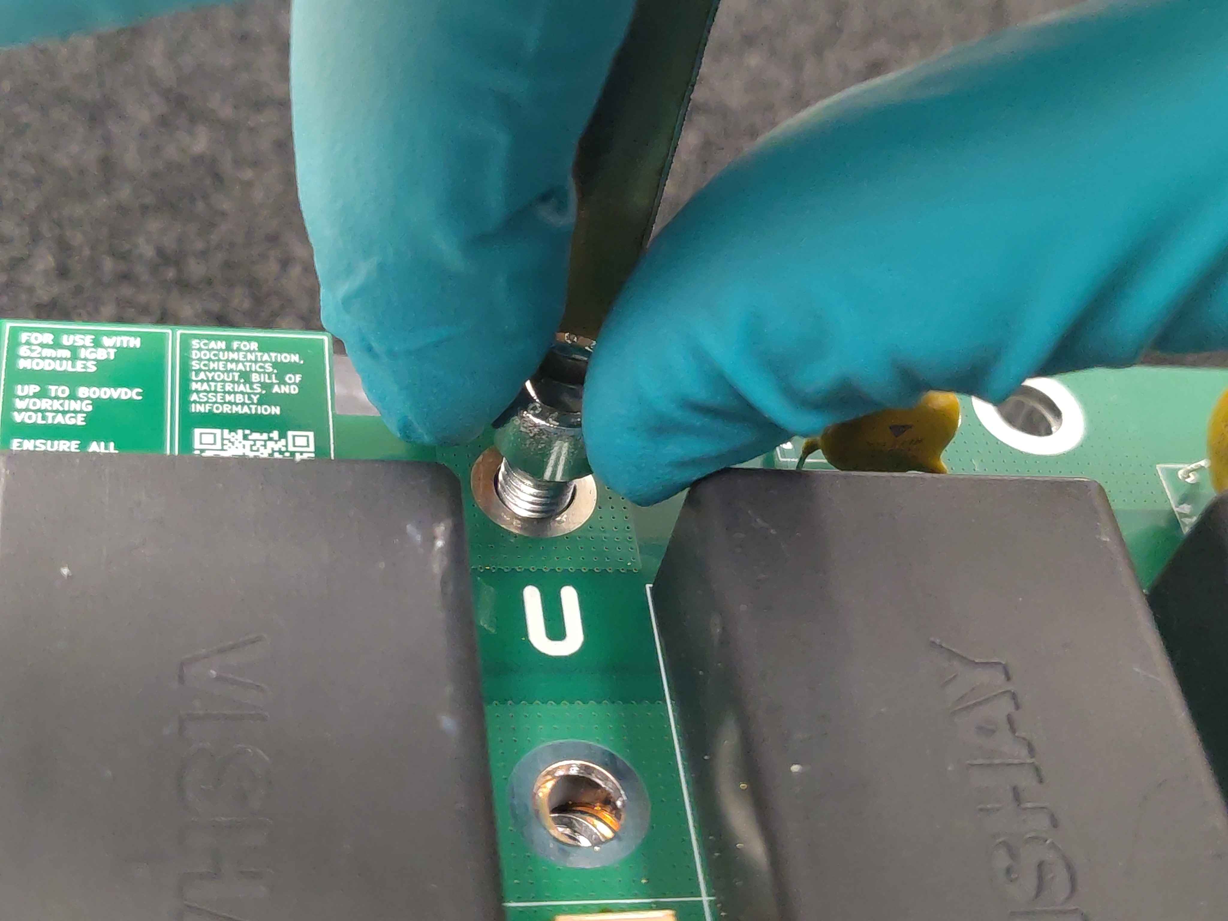
Step 8 - Insert the phase bus-bar screws
Drop one screw into each phase bus bar so it is ready to be tightened.
Carefully inserting a phase bus-bar screw
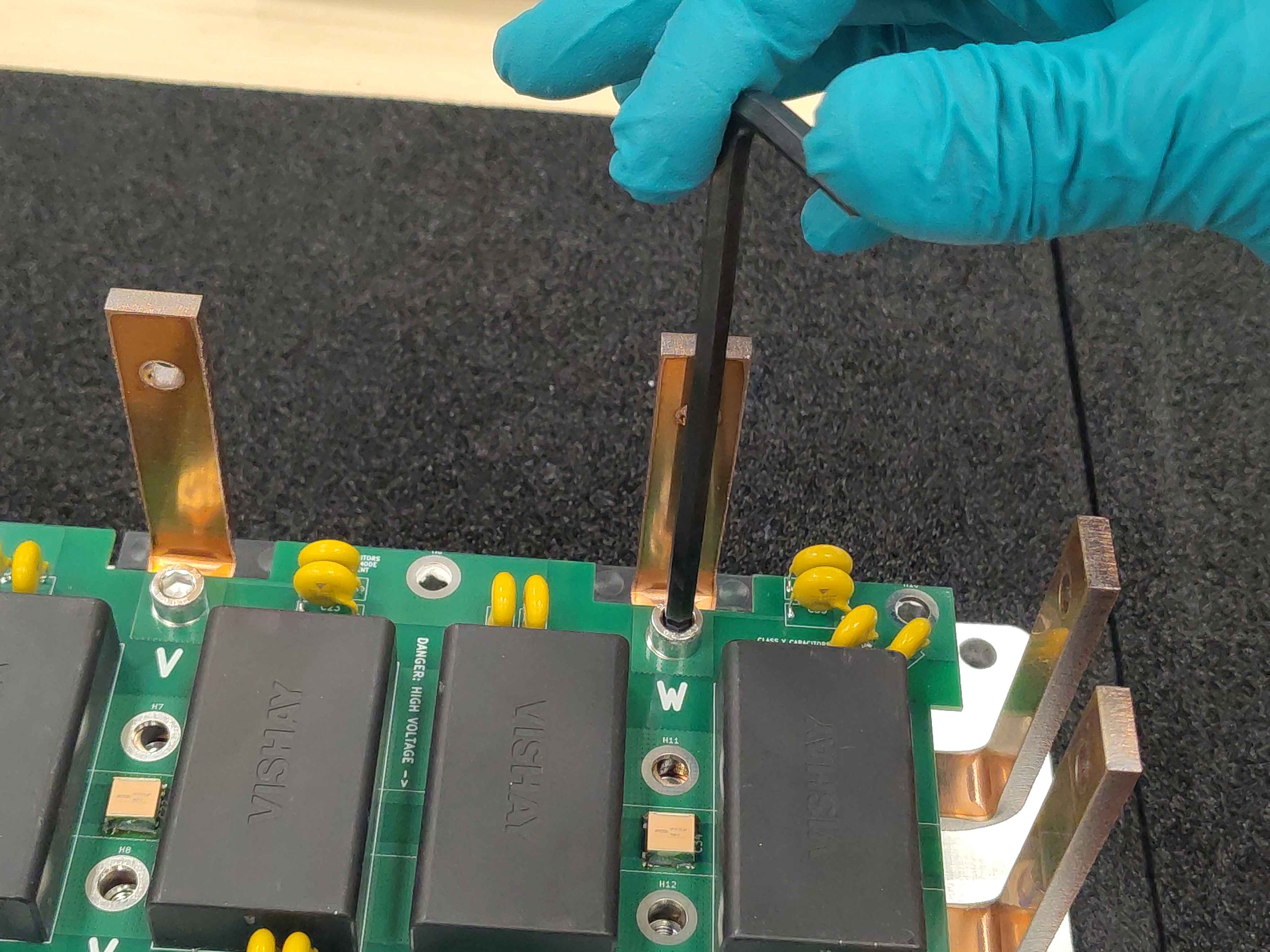
Step 9 - Hand-tighten the phase bus-bar screws
Hand-tighten each phase bus-bar screw only. Do not torque these screws now; they will be revisited and fully tightened once the rest of the assembly is bolted down and everything is aligned.
Warning: Do not use a power driver or apply significant torque at this stage. The assembly is still delicate and the final clamp-up happens later.
Hand-tightening a phase bus-bar screw for now
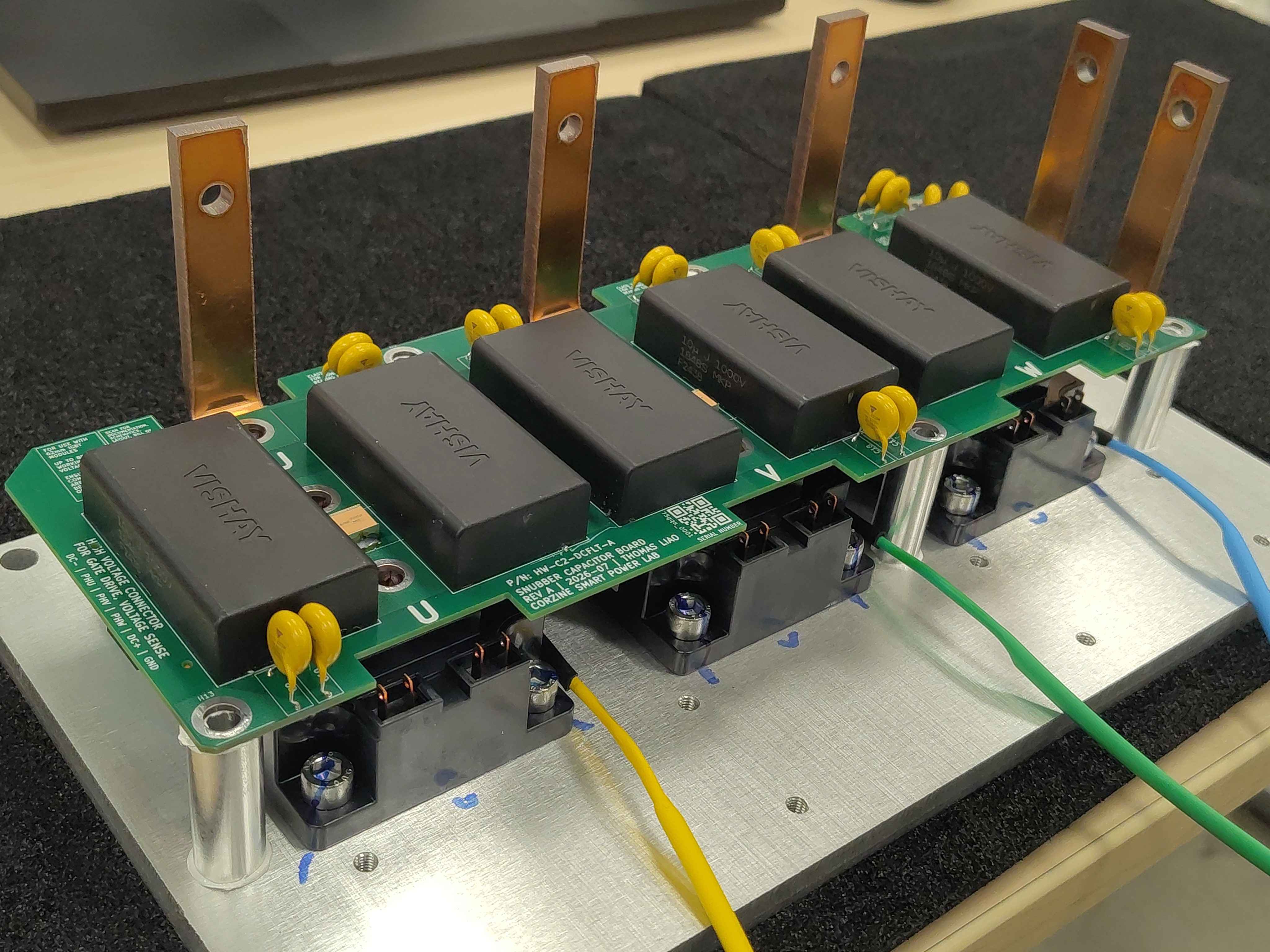
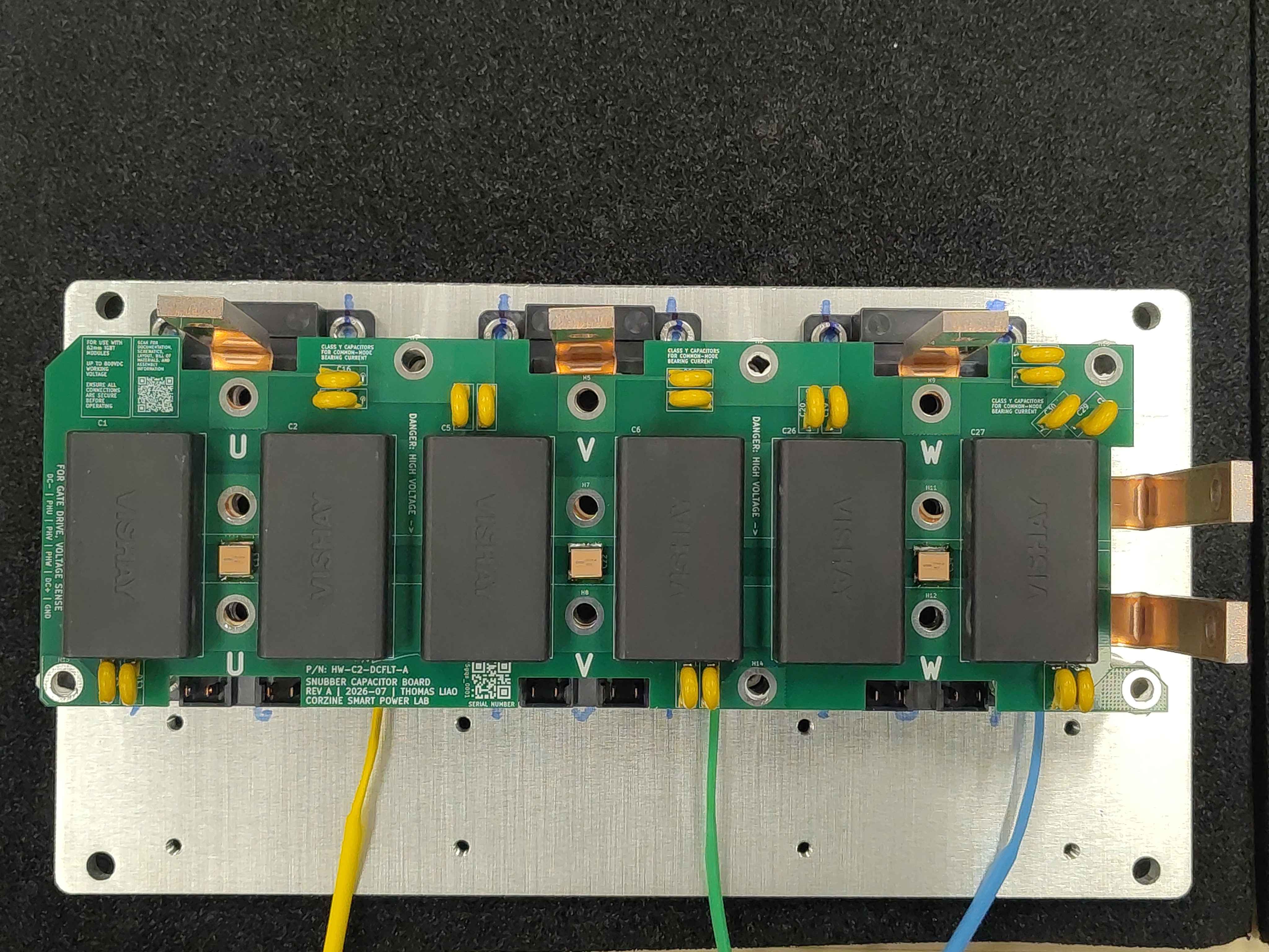
Final assembly
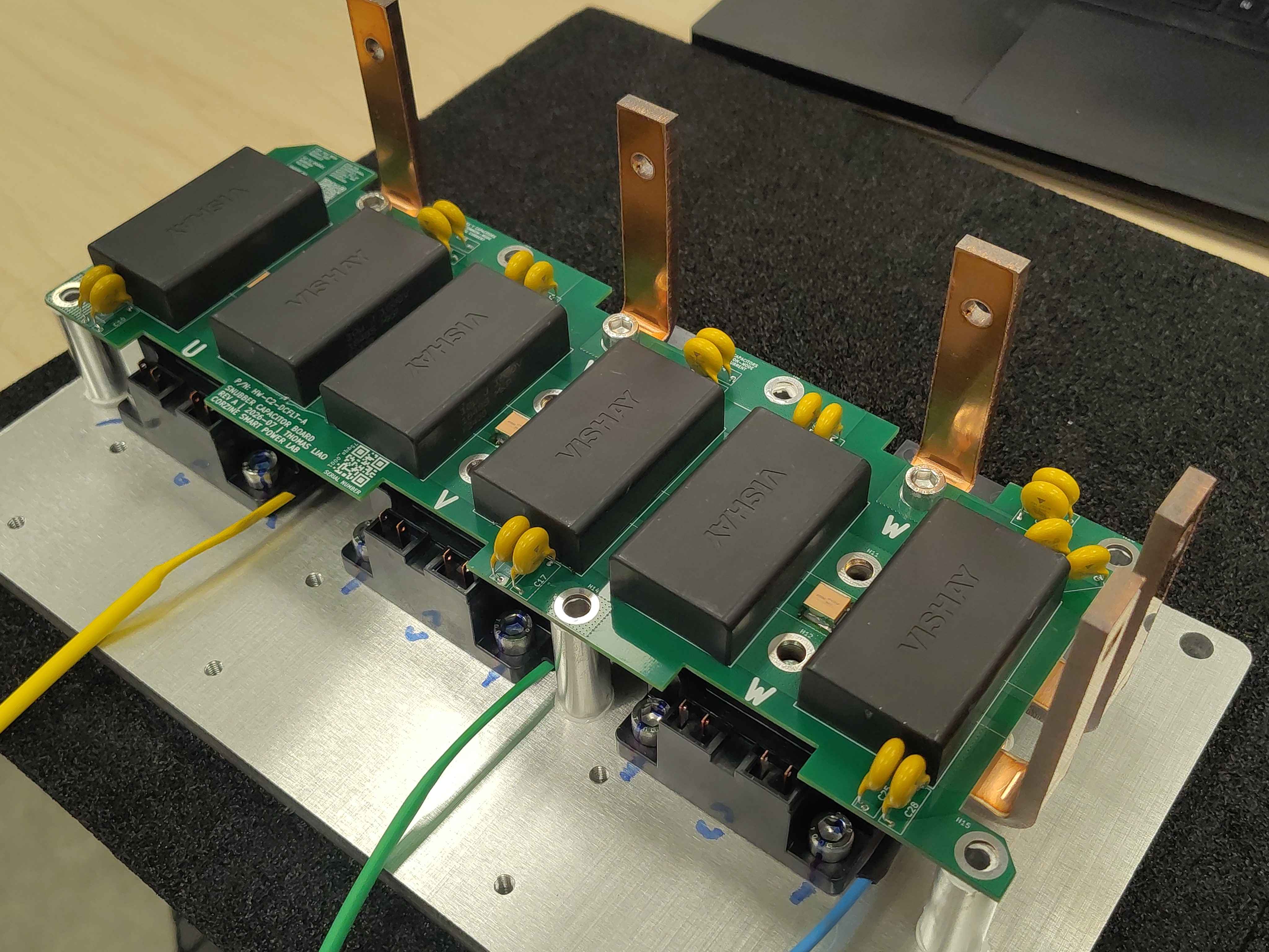
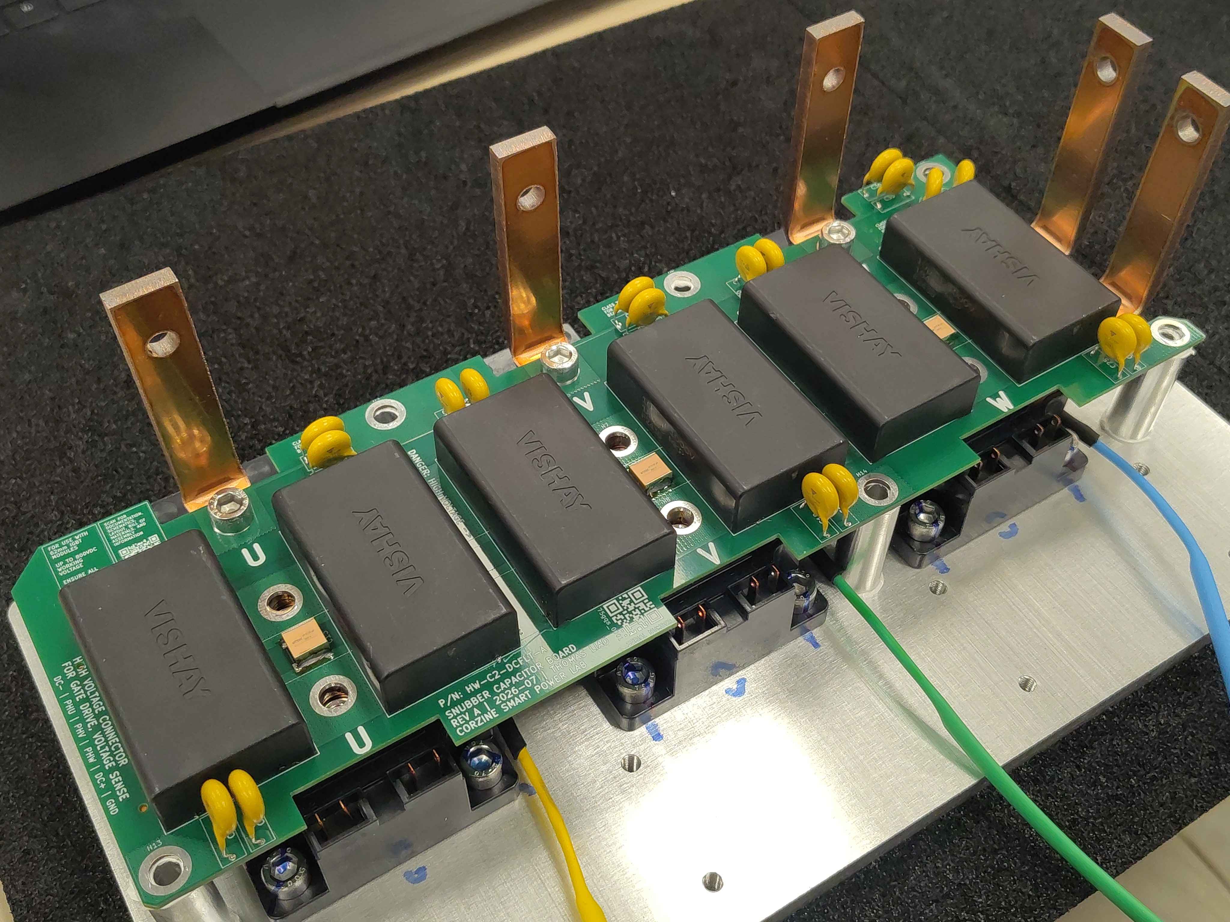
At this point the DC-link filter board, DC-link bus bars, and phase bus bars are all in place, but the assembly is not rigid:
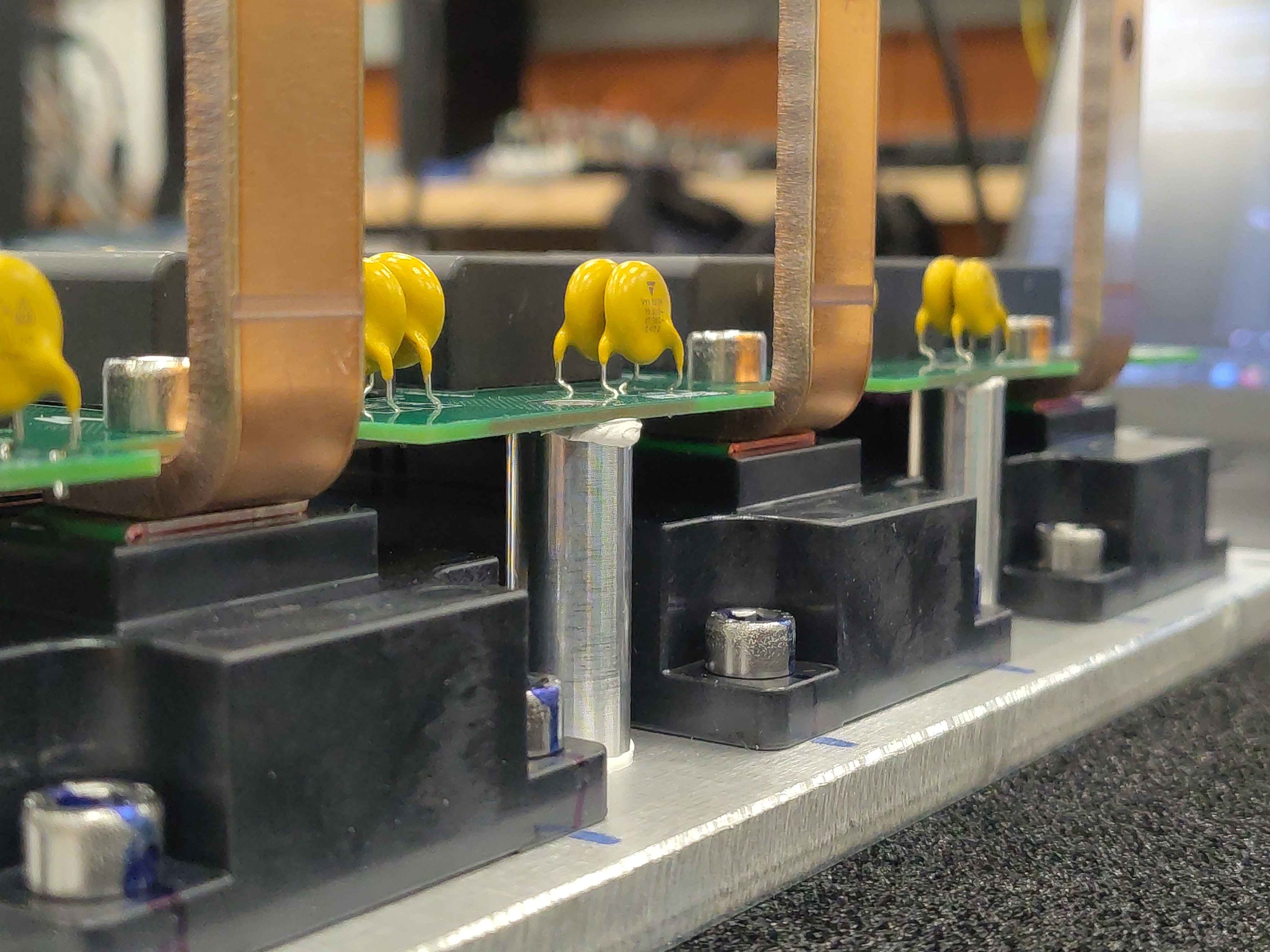
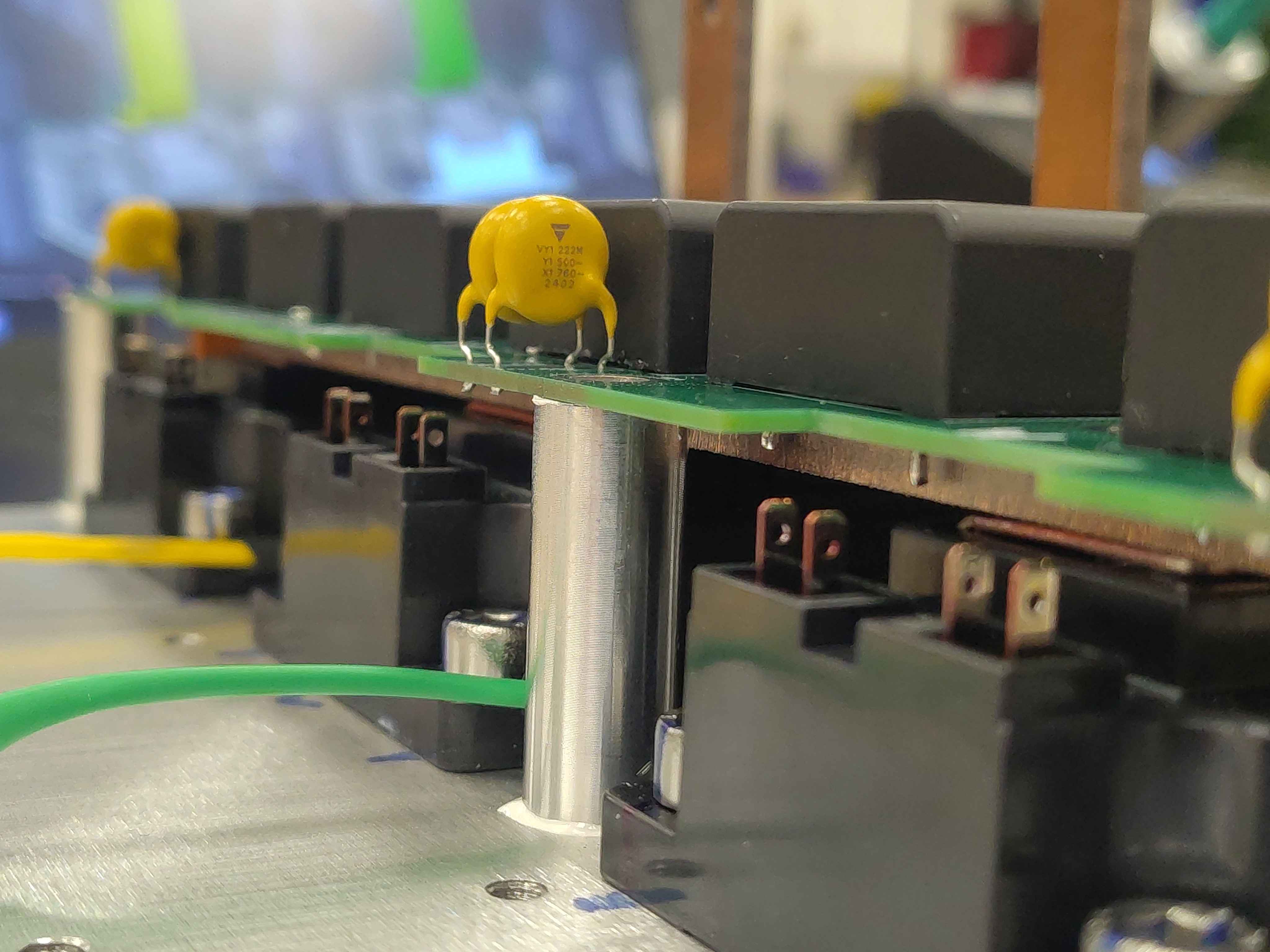
The bottom spacers are held in place by the weight of the filter board resting on top of them.
The DC-link bus bars are simply resting on the IGBT modules and can shift around.
The phase bus-bar screws are only hand-tight.
Avoid moving the assembly if possible. If you must move it, support it from underneath and do not lift it by the bus bars or filter board.
Keep the work area clear until the remaining chassis hardware is installed.
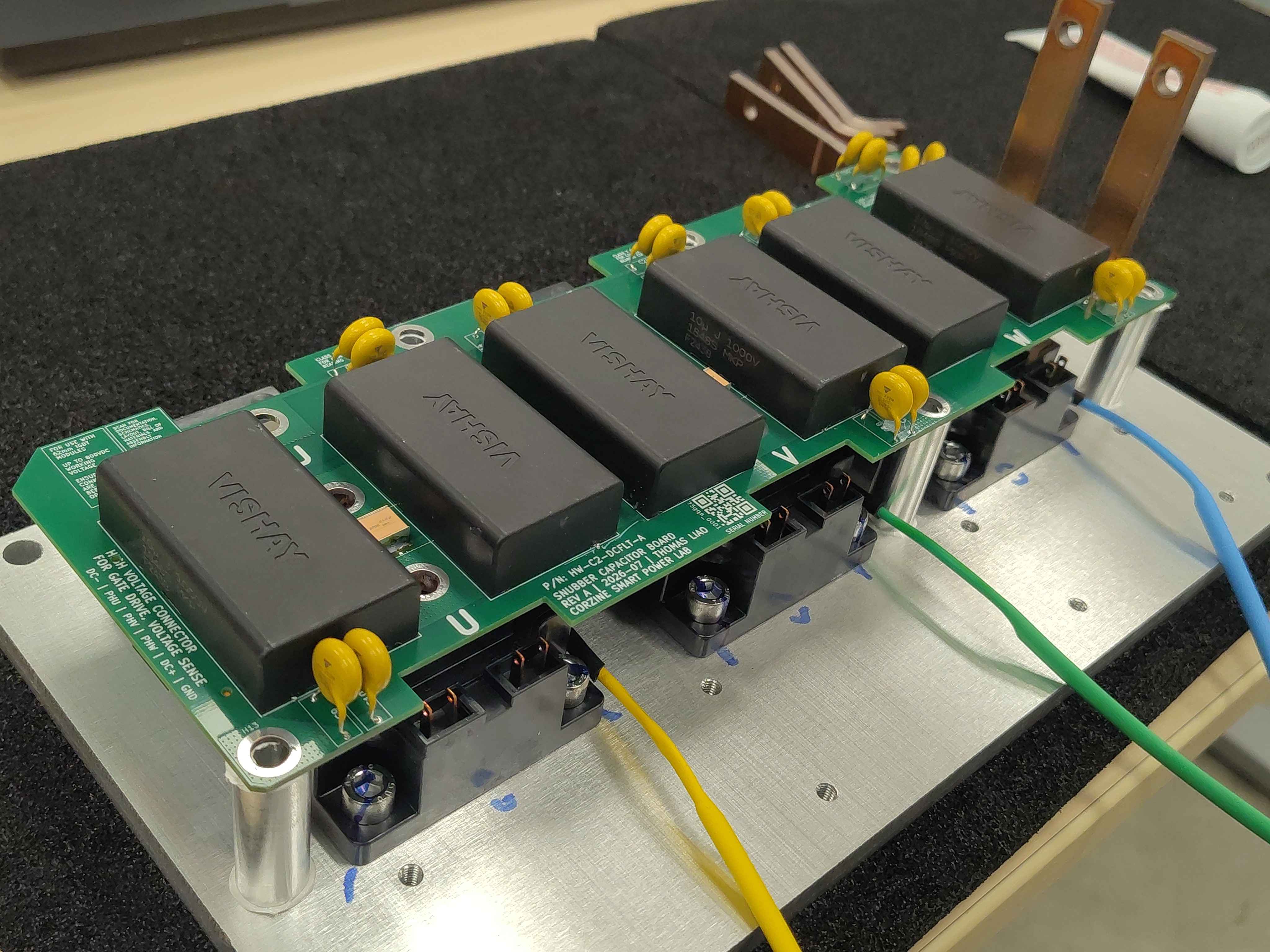
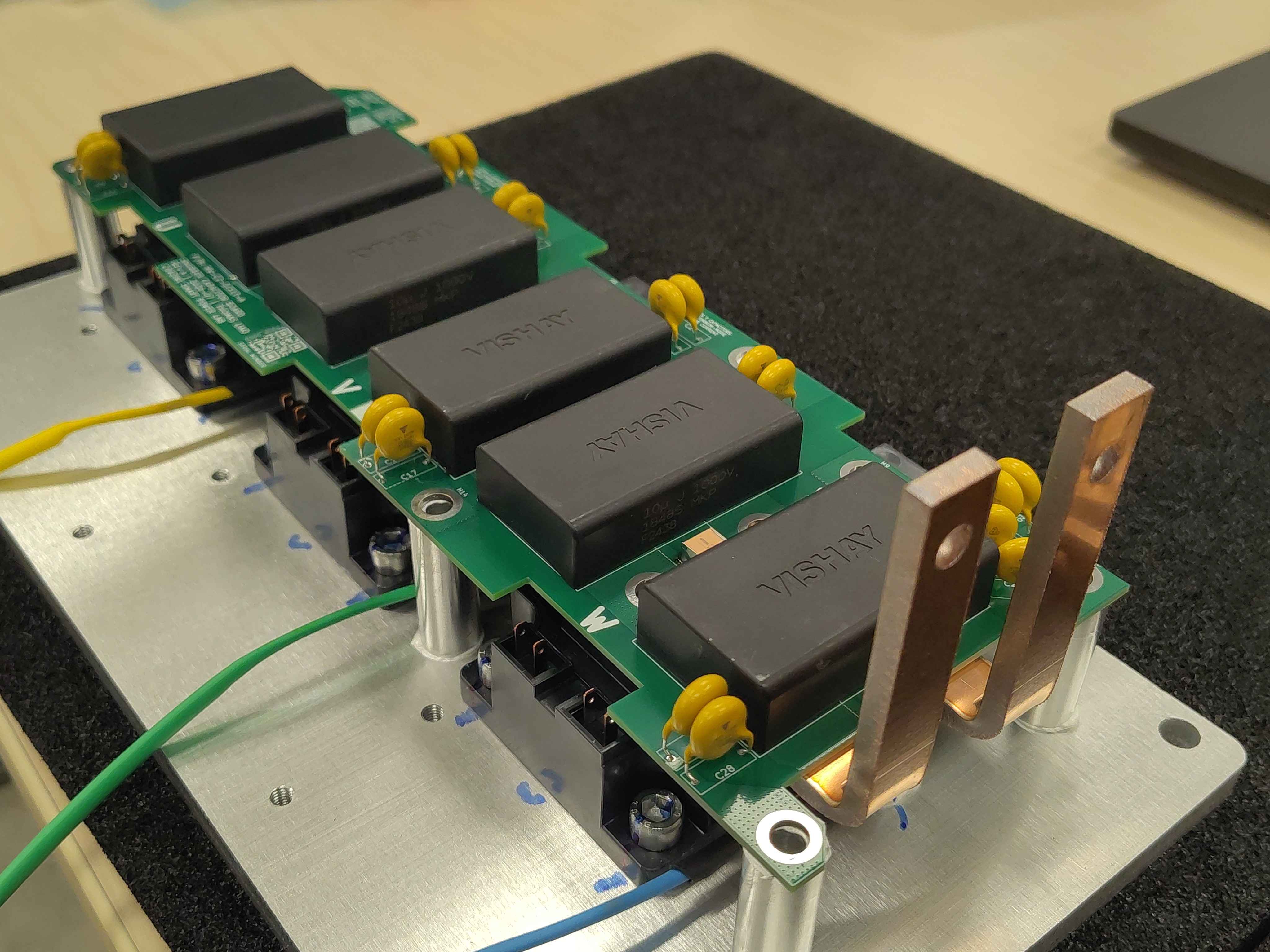
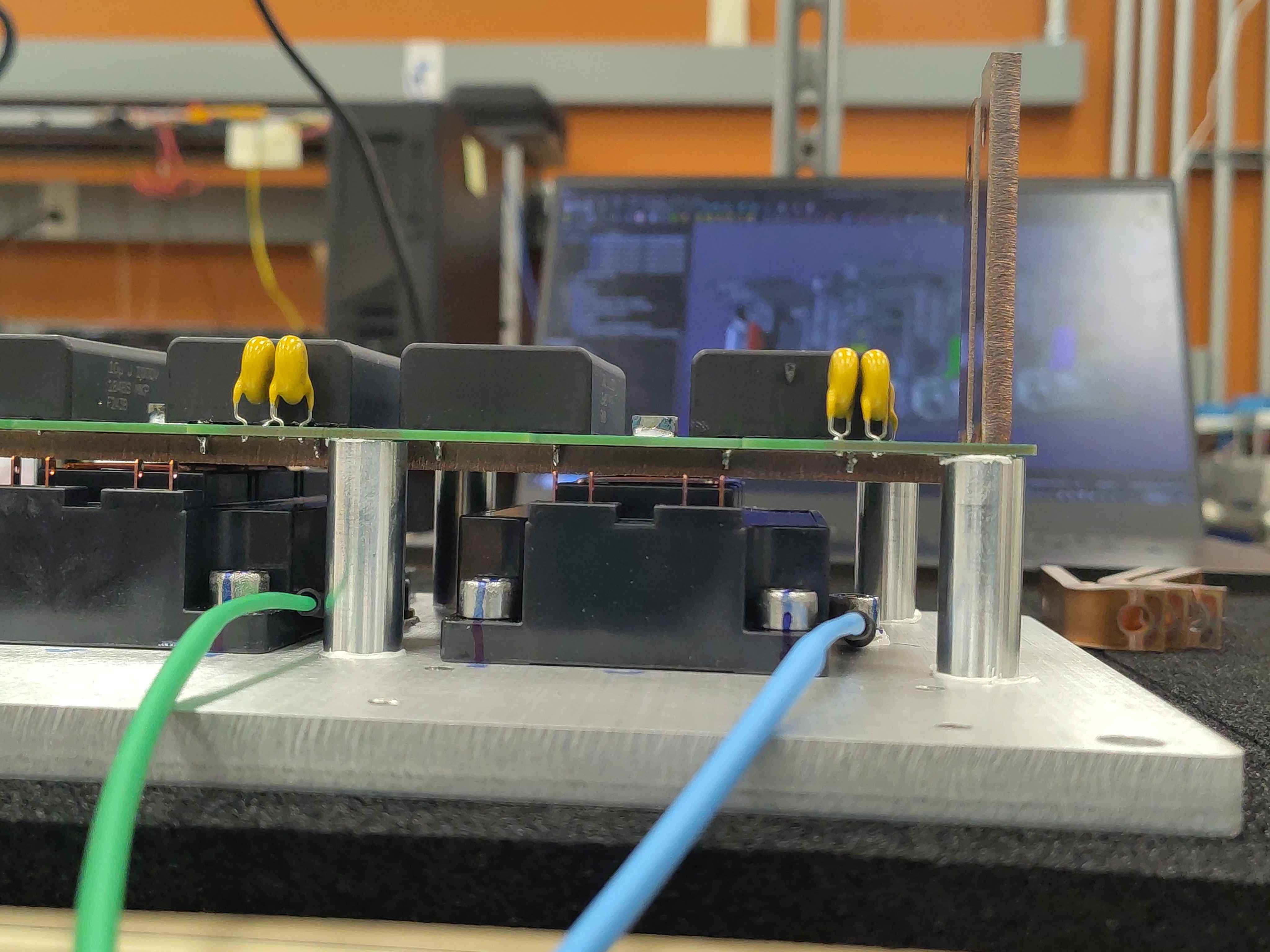
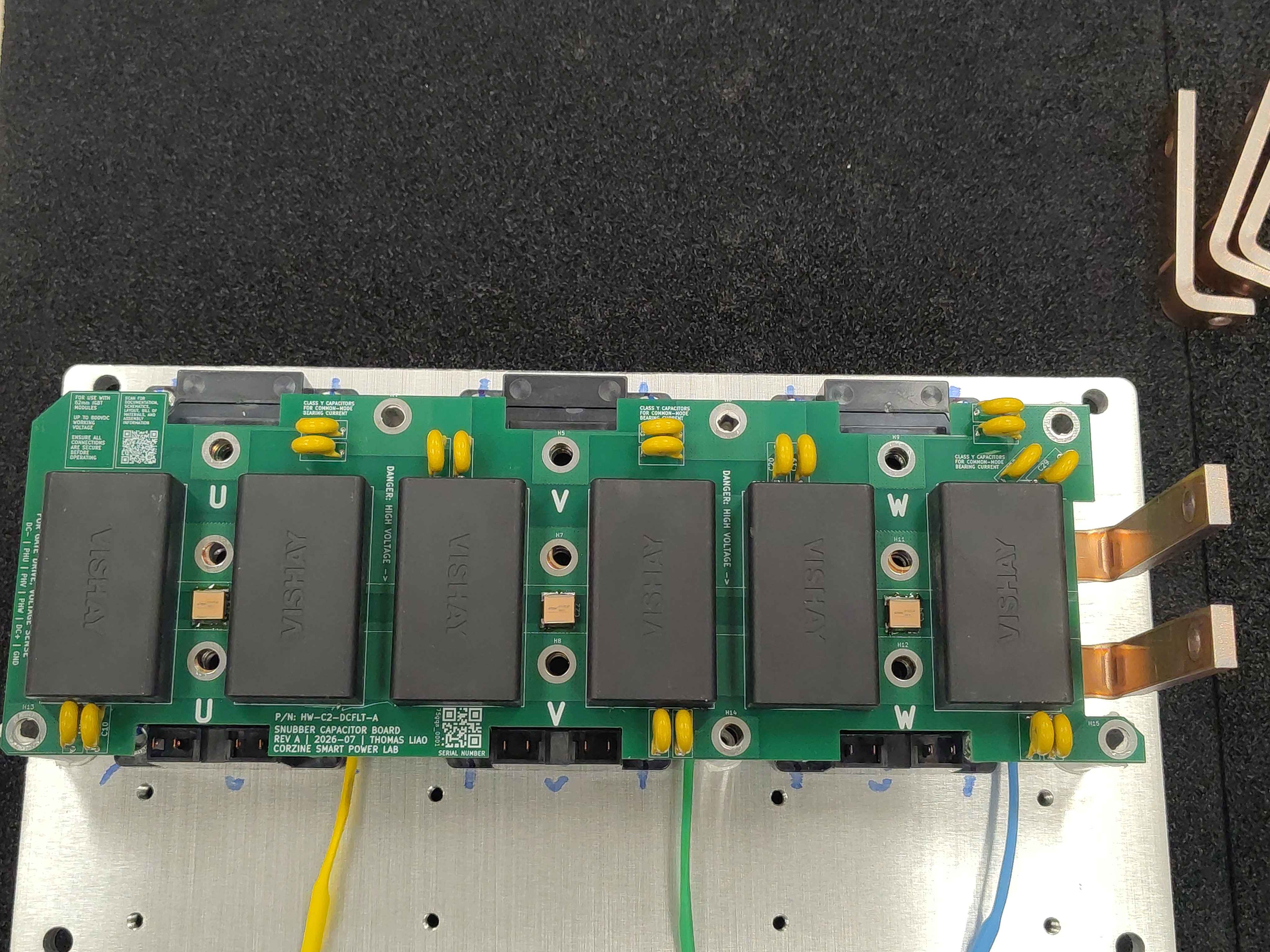
Final assembly view 1Final assembly view 2Final assembly view 3
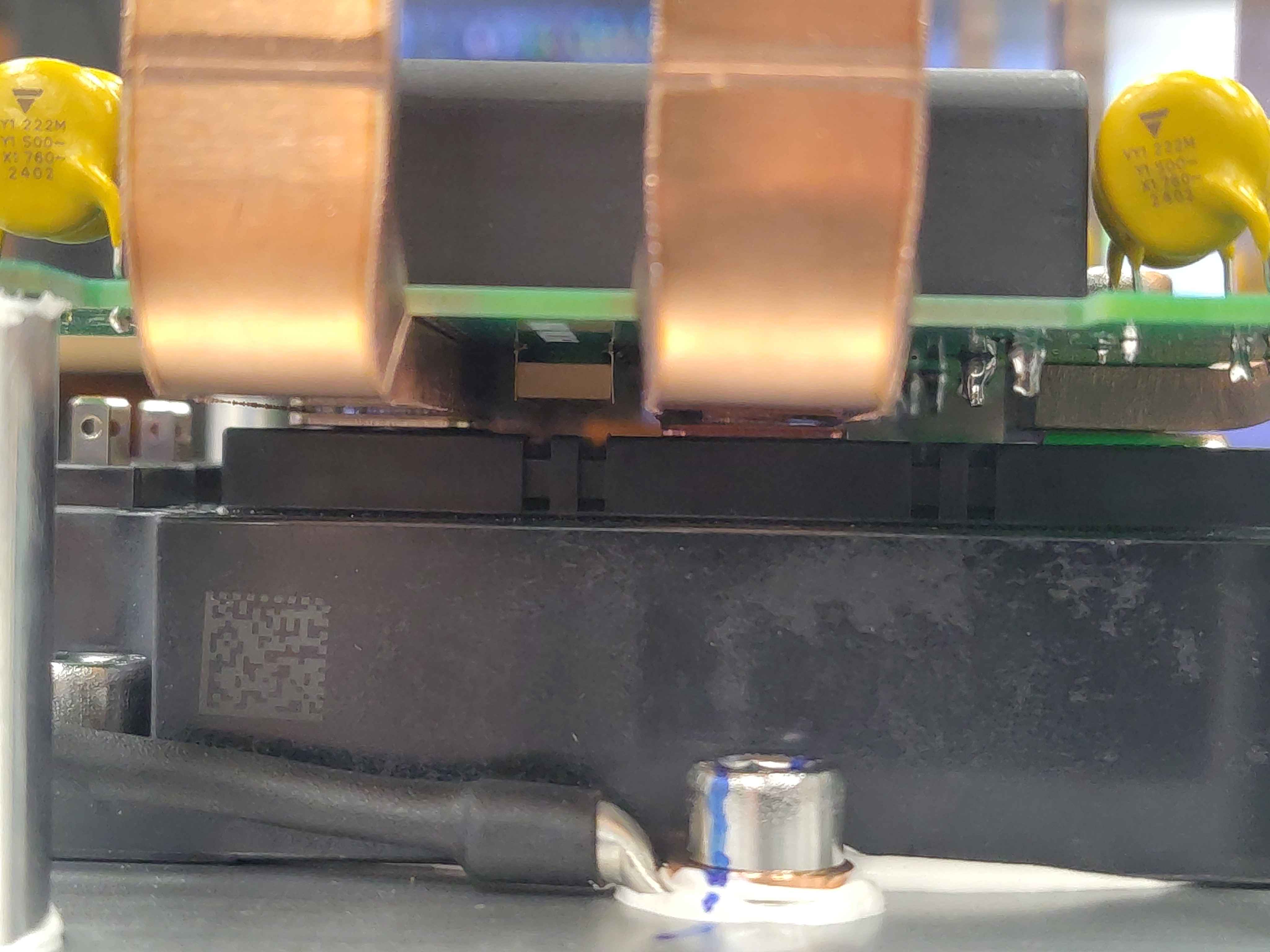
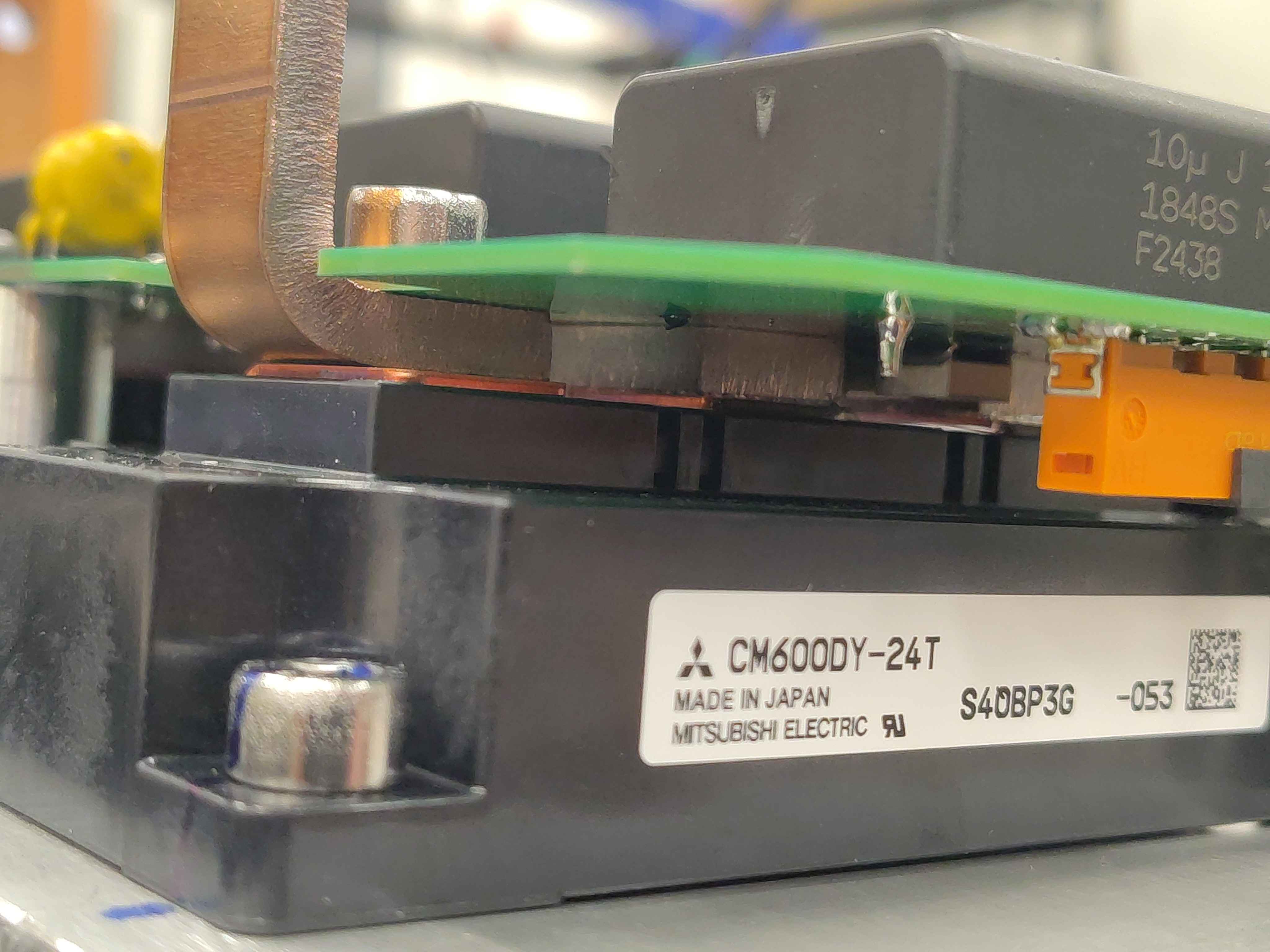
Note: In the photo above, the ceramic snubber capacitors sit directly between the module terminals. Keeping this loop as physically short as possible minimizes loop inductance.
Final assembly close-up 1Final assembly close-up 2Final assembly close-up 3
Next steps
Continue with the remaining Chassis Size 2 assembly steps in the assembly guide index (OV-C2-AG-INDEX). The phase bus-bar screws and other fasteners will be fully tightened in a later chapter once the module is fully stacked.