
15 · v0.3 · 2026-09-23Download PDF
| Doctype | Test Report |
|---|---|
| Product line | openvvvf |
| Applies to | openvvvf-control-module, chassis-size-2 |
| Version | 0.3 |
| Date | 2026-09-23 |
| Description | First Gen7 size 2 regenerative run at a 400 A q-axis command, using a Chroma DC load bank to clamp the bus at 150 V because the Sorensen supply sinks only about 50 A of regen. Hardware met every target. The apparent phase-current "spikes" observed on the oscilloscope at 400 A were subsequently attributed to the Tektronix current clamps (rated 150 A) saturating at the measured current — a measurement artifact, resolved in the follow-up 450 A report. |
| Test id | 15 |
| Nav order | 364 |
| Normative refs | OV-TEST-HW-INDEX, OV-TEST-HW-REGEN-200A-GEN7-SIZE2 |
Initial 400 A Regen Test — Gen7 Size 2
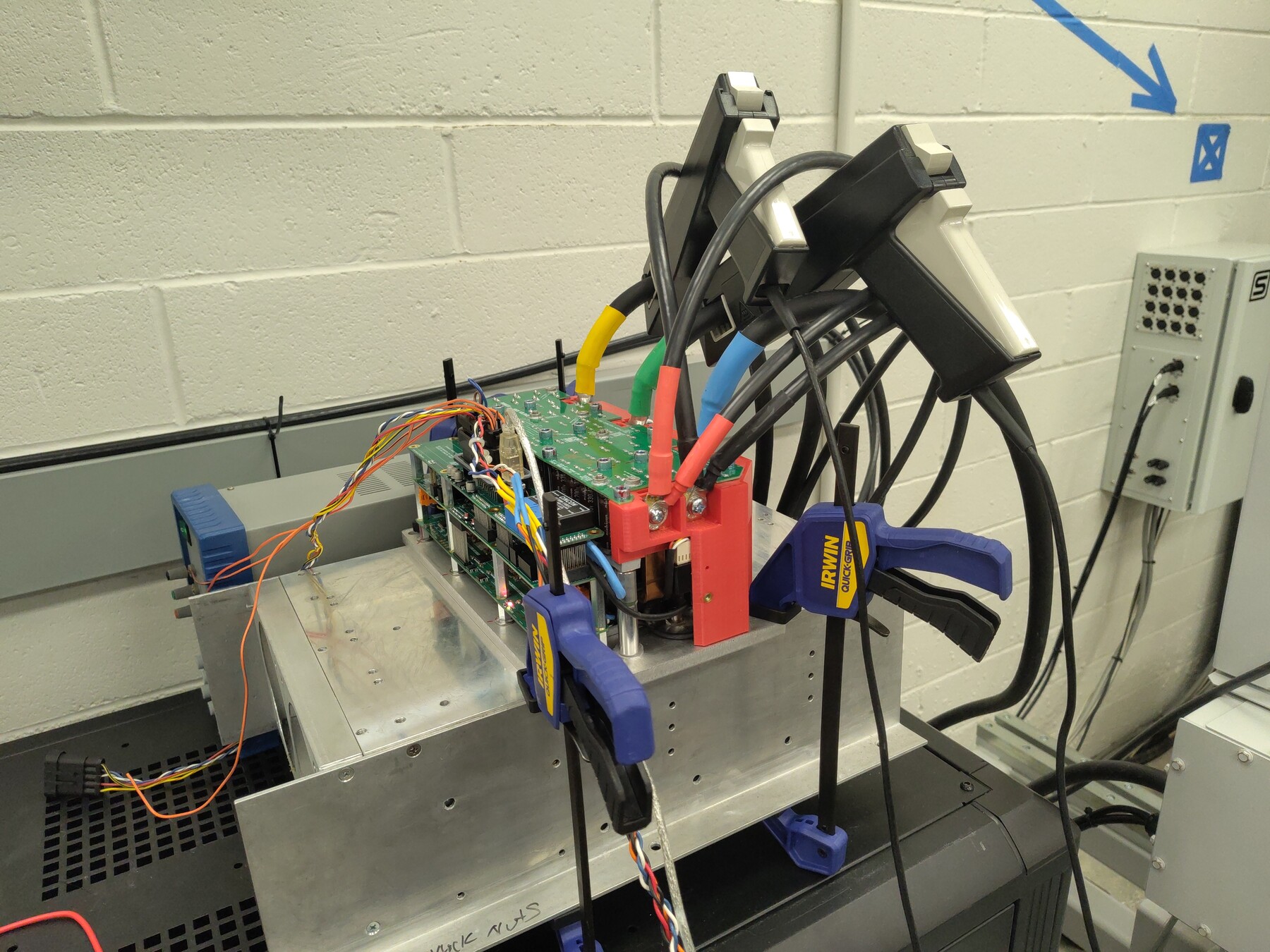
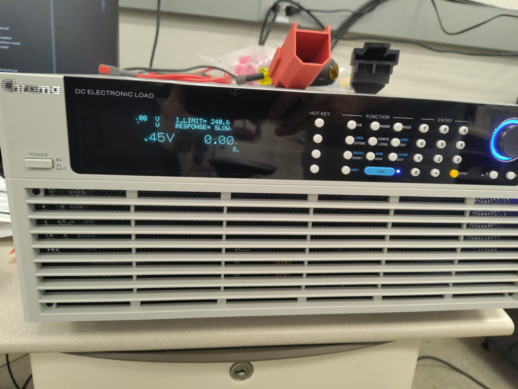
This report extends the Gen7 size 2 regenerative staircase of OV-TEST-HW-REGEN-200A-GEN7-SIZE2 from 200 A to a 400 A q-axis command. The limiting facility for high-current regen is the DC bus: the Sorensen bench supply can sink only about 50 A back into the grid, so above roughly 150 A of regen the bus voltage runs away. For this run a Chroma DC electronic load bank was connected across the DC link in constant-voltage mode at 150 V to absorb everything the supply cannot sink. The inverter was commanded in steps from 25 A to 400 A and held at 400 A twice, returning up to 8.8 kW to the DC link.
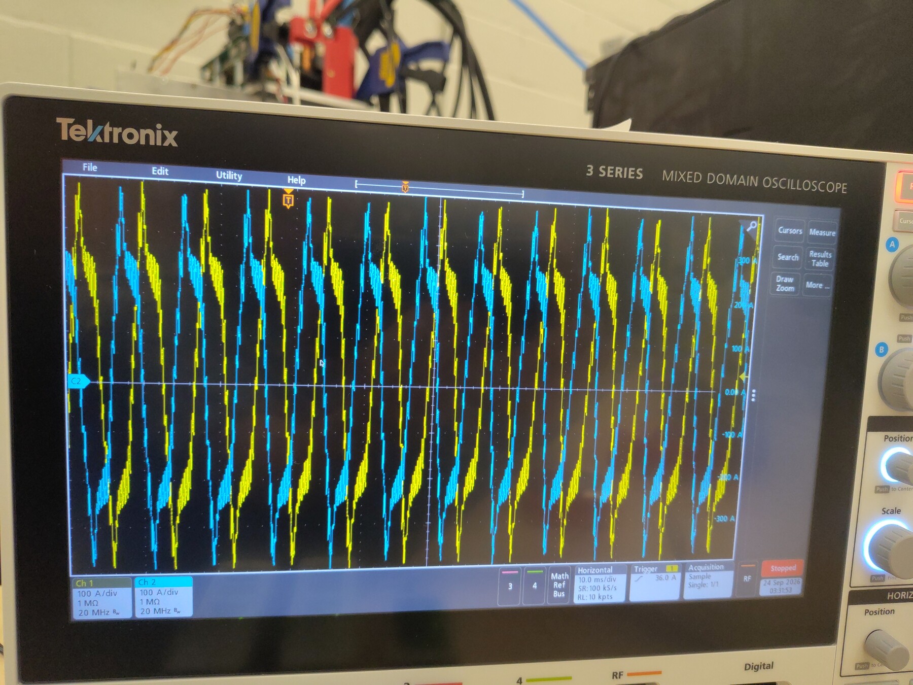
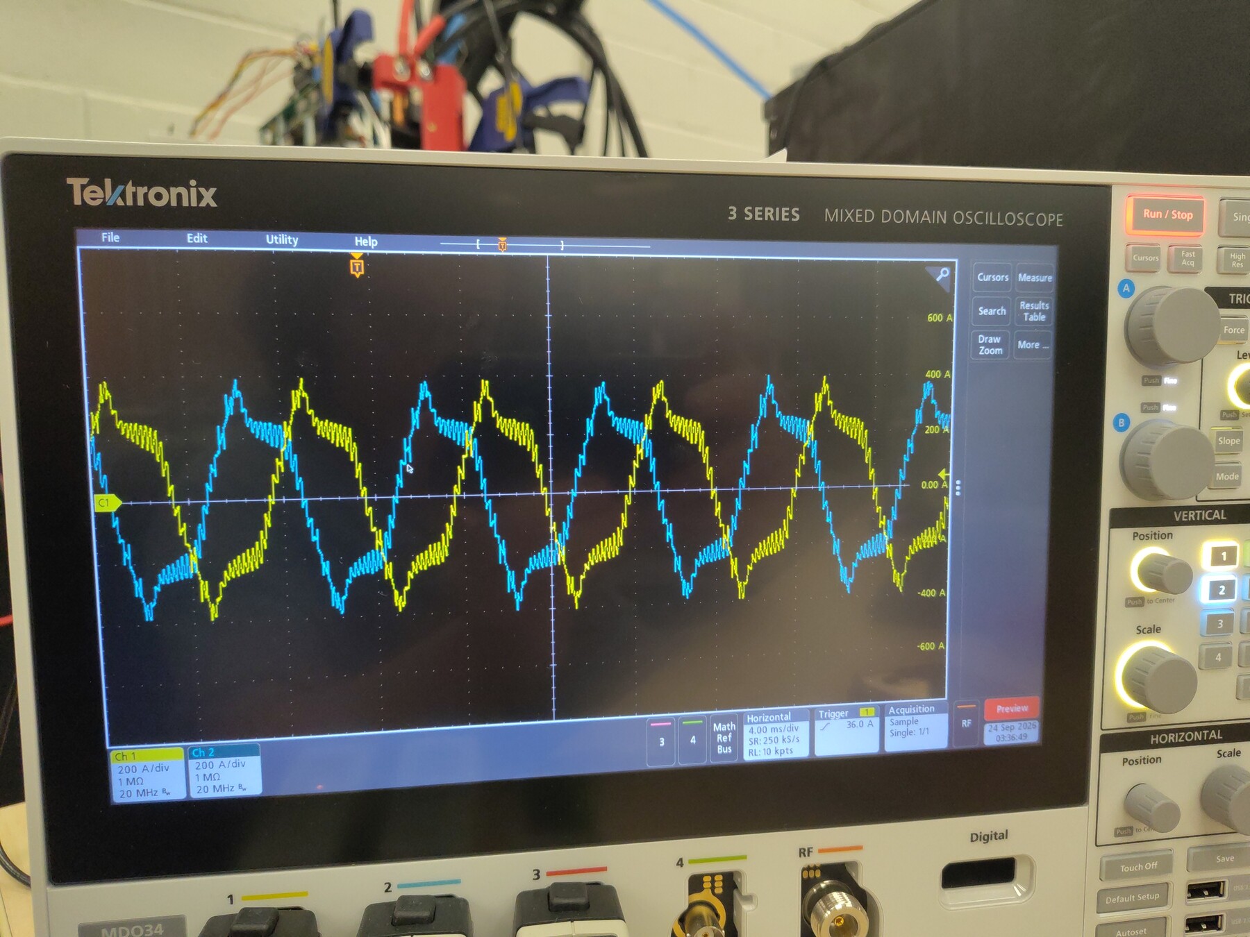
During the 400 A holds, narrow repetitive spikes were observed on the oscilloscope phase-current traces that were not present at lower currents. Telemetry shows clean control, no faults, and a solid 150 V clamp, so the anomaly is visible only in the analog captures and its cause is undetermined. The test was stopped for this reason. Hardware passed every target; the spike observation is resolved below — it was the oscilloscope current clamps saturating, not the inverter.
Test setup
- DUT: OpenVVVF Gen7 size 2 inverter hardware, firmware
foc_demograph (hash855dbcee90d611cb, includes slew-limitedIqVar, burst current sampling, and a modulator voltage-limit node). - Machine: Induction machine coupled to a Sierra CP Engineering dynamometer; approximately −1,470 RPM mechanical (−7,360 RPM electrical) during the holds.
- DC supply: Sorensen bench supply (regenerative sink limited to ~50 A) in parallel with a Chroma DC electronic load bank in constant-voltage mode at 150 V across the DC link, clamping the bus.
- Instrumentation: RTE Studio telemetry, Tektronix 5 Series MSO, Chroma load front panel.
- Temperature channels: baseplate NTCs TS1 (
temp_inv1_c) and TS2 (temp_inv2_c); TS3 (temp_inv3_c) was not enabled for this session due to a wiring defect unrelated to the test.
Test conditions
| Parameter | Value |
|---|---|
| Hardware | Gen7 size 2, firmware foc_demo hash 855dbcee90d611cb |
| Machine speed | ~−1,470 RPM mech (−7,360 RPM elec) |
| Bus baseline | ~74 V |
| Bus clamp | Chroma CV at 150 V; held 149.6–151.8 V during both 400 A holds |
| Current command | IqVar staircase 25–200 A in 25 A steps, then 250/300/350/375/400 A |
| Time at 400 A | 14.8 s first hold; ~31 s at full current second hold (39.0 s including ~8 s slew-limited ramp) |
| Peak phase current | 415 A |
| Peak DC-link power | 8.78 kW |
| Regen energy into DC link | ≈0.117 kWh total (0.034 kWh + 0.083 kWh across the two holds) |
| Machine terminal real power P | −8.39 kW (hold 1) / −7.52 kW (hold 2, Iq mean 356 A) — calculated from logged cg_vd_v/cg_vq_v/cg_id_a/cg_iq_a |
| Machine reactive power Q | ≈5.0 / 4.3 kvar (hold 1 / 2; machine magnetizing demand, quoted as magnitude) |
| Power factor (calculated) | 0.86 / 0.88 (hold 1 / 2) |
| Inverter efficiency (calculated) | ≈100% in both holds (telemetry-resolution limited at this power) |
| Peak baseplate NTC | 63.9 °C (TS1), 59.5 °C (TS2) |
| DC-link current | ~54–58 A during the holds (supply at sink limit; Chroma absorbs the rest) |
Procedure
- Enabled the inverter and allowed the dynamometer to bring the coupled machine to operating speed.
- Jogged
IqVarat 10 A and 26 A to confirm orientation, then stepped 25 → 200 A in 25 A steps, then 250/300/350/375/400 A. - Observed the bus climb from ~74 V as regen power exceeded the supply's sink capability, with the Chroma load bank absorbing the excess and clamping the bus at 150 V from the 375–400 A region onward.
- Held 400 A for 14.8 s (first hold). Narrow spikes were observed on the oscilloscope phase-current traces that had not been present at lower currents. Stopped the run (
IqVar 0) to investigate; becauseIqVaris slew-limited, current decayed to under 20 A in ~7.7 s. - Resumed with a second 400 A hold (39.0 s total including the ~8 s slew-limited ramp). The spikes were still present. Stopped again and let the inverter cool while logging continued to t = 340 s.
Electrical results
Per-command statistics from the full-rate telemetry log (Pdc = DC-link power, Idc = DC-link current):
| Iq command | Step duration | Avg Iq | Peak phase current | Avg Pdc | Avg Idc |
|---|---|---|---|---|---|
| 25 A | 2.2 s | 24.8 A | 31 A | 707 W | 9.5 A |
| 50 A | 2.4 s | 48.9 A | 57 A | 1.24 kW | 17 A |
| 75 A | 2.0 s | 70.6 A | 81 A | 1.73 kW | 23 A |
| 100 A | 2.8 s | 97.6 A | 110 A | 2.36 kW | 32 A |
| 125 A | 1.9 s | 121.8 A | 137 A | 3.14 kW | 42 A |
| 150 A | 4.8 s | 148.1 A | 161 A | 3.83 kW | 51 A |
| 175 A | 1.6 s | 170.5 A | 187 A | 4.27 kW | 53 A |
| 200 A | 8.8 s | 199.0 A | 212 A | 4.96 kW | 54 A |
| 250 A | 6.0 s | 245.3 A | 260 A | 5.84 kW | 54 A |
| 300 A | 7.0 s | 296.0 A | 305 A | 6.82 kW | 54 A |
| 350 A | 9.3 s | 347.1 A | 359 A | 7.67 kW | 54 A |
| 375 A | 5.9 s | 373.5 A | 384 A | 8.08 kW | 54 A |
| 400 A hold 1 | 14.8 s | 399.4 A | 415 A | 8.41 kW | 56 A |
| 400 A hold 2 (incl. slew ramp) | 39.0 s | 357.5 A | 415 A | 7.58 kW | 53 A |
The bus voltage told the clamp story directly: it stayed at 74.3–74.8 V through the 150 A step, began climbing at 175 A (74.3–82.3 V), and rose stepwise to the Chroma clamp (142.5–150.4 V at the 375 A step), then held 149.6–151.8 V through both 400 A holds. Above ~150 A of regen the logged DC-link current pinned at ~54–58 A — the Sorensen at its sink limit — while the power increase showed up entirely as bus voltage until the Chroma clamp took over. The modulator voltage limiter never engaged (cg_vlimit_scale = 1.000 for the entire session); all clamping was external. Current control tracked cleanly: raw and filtered Iq agree, and hold 2 averaged 357.5 A only because its window includes the ~8 s, ~50 A/s slew-limited ramp from the IqVar 400 re-application to full current.
- Machine-terminal power (calculated): from the logged dq quantities (peak-amplitude convention, P = (3/2)(vd·id + vq·iq), Q = (3/2)(vq·id − vd·iq)). Hold 1: the machine delivered 8.39 kW while drawing ≈5.0 kvar (9.74 kVA, PF ≈ 0.86); hold 2: 7.52 kW and ≈4.3 kvar (8.67 kVA, PF ≈ 0.88). Machine-terminal and DC-link power agree within ~0.3% in both holds — calculated inverter efficiency ≈ 100%, telemetry-resolution limited at this power (the same calculation shows ≈95% at 13 kW in the 450 A run, where the loss is larger than the measurement offsets).
Thermal results
Temperatures were benign for the full session:
- Baseplate TS1 (
temp_inv1_c): 28.1 °C start, 53.0 °C at the end of the first hold, 63.9 °C peak at t ≈ 203 s (just after the second stop — the thermal peak lags the power). - Baseplate TS2 (
temp_inv2_c): 31.2 °C start, 59.5 °C peak at t ≈ 202 s. - Both channels cooled to ~41–43 °C by the end of logging. TS3 was not enabled for this session (wiring defect, unrelated to the test) and
temp_motor_cis unpopulated in this recording.
Current-spike observation
Resolved — measurement artifact, not an inverter anomaly. During the first 400 A hold, the oscilloscope showed narrow, repetitive spikes superimposed on the phase-current waveforms, concentrated near the current peaks (photos above); they were not observed at lower currents. The cause, established during the follow-up 450 A run, is the measurement channel: the Tektronix current clamps are rated at 150 A and clipped/saturated at the 400 A phase currents, producing exactly this kind of spiked, distorted trace. See OV-TEST-HW-REGEN-450A-GEN7-SIZE2 for the follow-up run and resolution note.
The telemetry evidence from this session is consistent with that conclusion:
- The ~56 Hz telemetry publish rate cannot resolve waveform-scale spikes: the electrical frequency is ~123 Hz, so per-sample phase-current values are aliased by design.
- Everything is clean: all 19,012 current samples valid (
cg_sample_valid),gate_fault= 0 for the entire session, no desaturation events,cg_vlimit_scale= 1.000 throughout, the bus sat solidly on the 150 V clamp, and Iq tracking was tight in both holds — none of which would be expected if the spikes were a power-stage or control phenomenon.
No further investigation of the inverter is required on this observation; future sessions should use current transducers rated for the measured current.
Telemetry overview
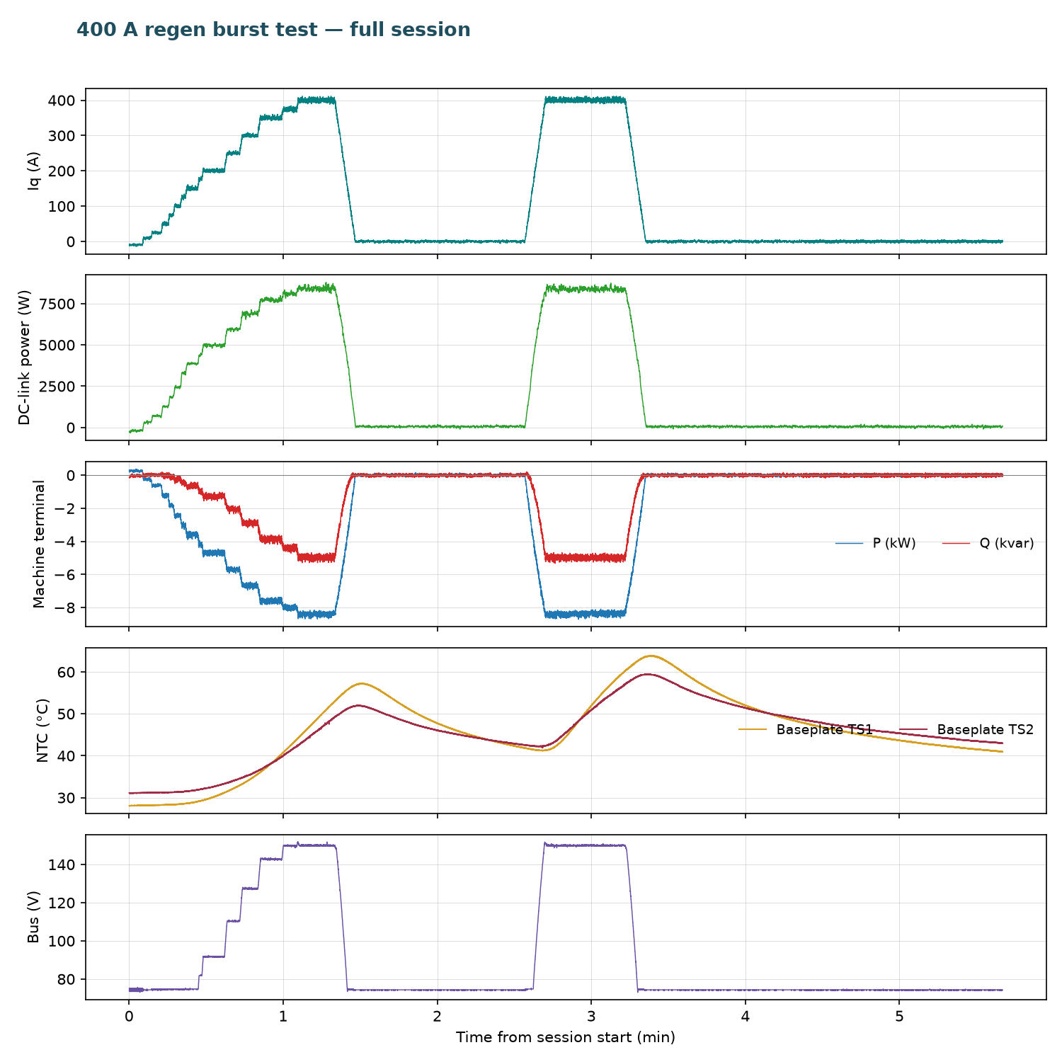
Open full session: View the run in the Telemetry Viewer
Observations
- The Chroma load bank solved the facility limit: with the Sorensen sinking ~50 A, the 150 V CV clamp absorbed the remainder and made the 300–400 A steps possible at all.
- Above ~150 A of regen, DC-link current pinned at the supply's sink limit and further power increase appeared as rising bus voltage until the clamp.
- The stop command does not cut current quickly:
IqVar 0slews down at the configured rate, reaching under 20 A in ~7.7 s. Emergency expectations should account for this. - After each stop the bus collapsed from 150 V back to ~74 V in about 5 s as the Chroma stopped drawing.
- A
UartErrorfault flag (0x200) was active from before the first command and throughout the session. Telemetry quality was unaffected (45 bad frames of ~767 k); it is treated as a latched host-link flag, not a run-affecting fault.
Conclusion
Pass. Gen7 size 2 hardware sustained a 400 A q-axis regenerative command — 415 A peak phase current, 8.78 kW peak DC-link power, ≈0.117 kWh returned — with the bus clamped at 150 V by the added Chroma load bank, no gate or control faults, and baseplate temperatures below 64 °C. The repetitive phase-current spikes observed on the oscilloscope at 400 A were subsequently determined to be the 150 A-rated Tektronix current clamps saturating at the measured current — a measurement artifact, not an inverter anomaly (see the 450 A follow-up report).
Artifacts
- Decimated telemetry log (JSONL, 1 sample/s) — open in Telemetry Viewer
- Telemetry overview plot
- Full source telemetry log, retained for traceability
- Photos: phase currents on scope, zoomed spike detail, bench with Chroma wiring, Chroma load bank front panel
- Full-resolution originals of the photos are retained alongside as
*-Original.jpg.