
12 · v0.2 · 2026-09-22Download PDF
| Doctype | Test Report |
|---|---|
| Product line | openvvvf |
| Applies to | openvvvf-control-module, chassis-size-2 |
| Version | 0.2 |
| Date | 2026-09-22 |
| Description | Twenty-two-minute continuous regenerative braking at a 100 A q-axis current step on a dynamometer-spun machine, run with the bare C2 power stage (no heatsink, no fan) to prove phase-current endurance and capture thermals. |
| Test id | 12 |
| Nav order | 359 |
| Normative refs | OV-TEST-HW-INDEX |
Low-Power Regen 100 A Phase-Current Endurance (No Cooling)
This report records a regenerative-braking endurance run on the OpenVVVF C2-class power stage. A Sierra CP Engineering dynamometer spun the coupled machine at ~280 RPM while the inverter applied negative q-axis current in 10 A steps up to −100 A, then held −100 A for 22 minutes. The point of the test is in the name: the DC bus was only ~52 V, so 100 A of phase current amounts to roughly 300 W of electrical power — full phase-current stress at very low power — and the bare board stack ran with no heatsink and no forced-air cooling the entire time.
Test setup
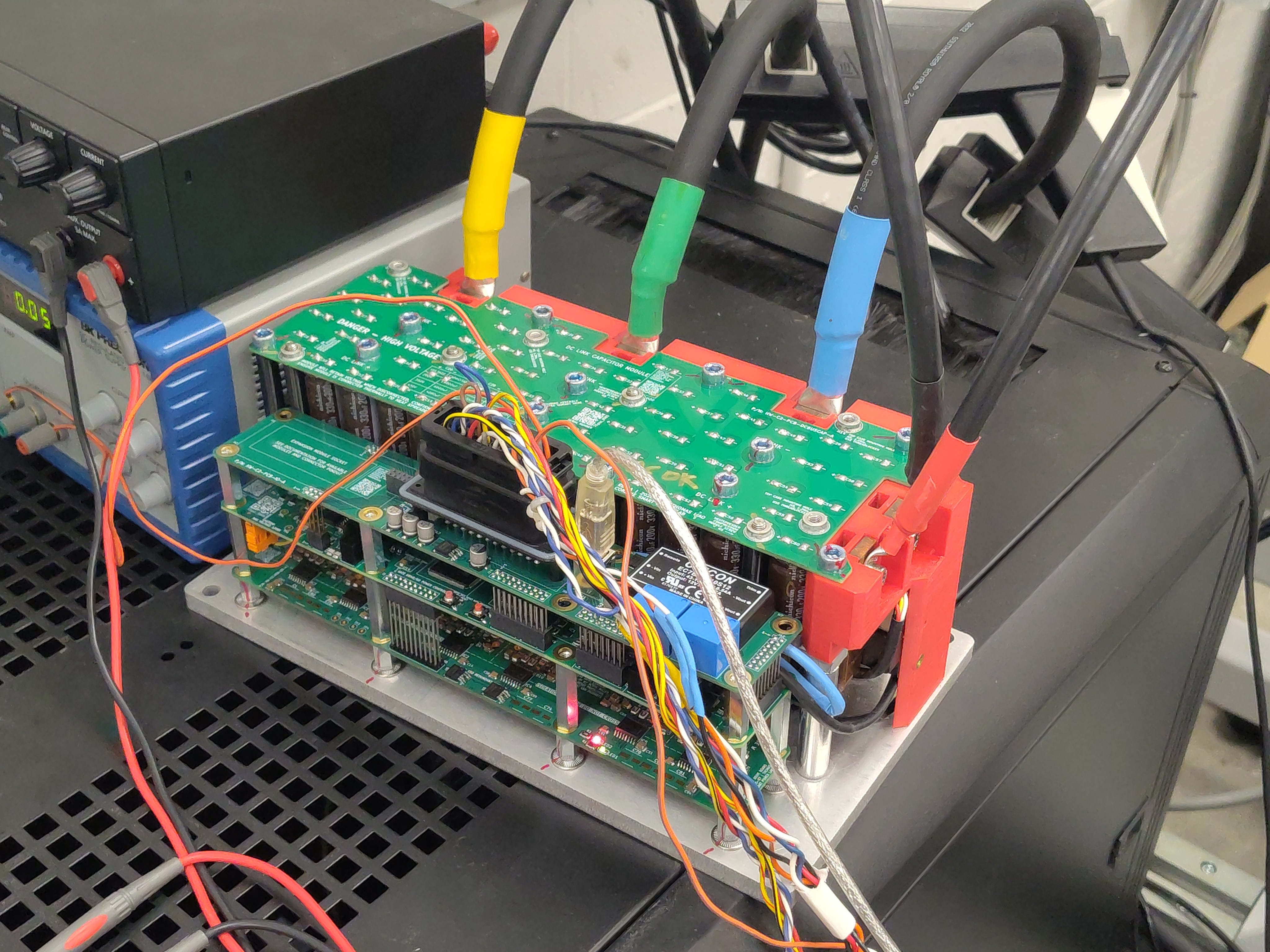
- DUT: OpenVVVF control module on a C2-class power stage with the dynamometer termination/connection board (silkscreen Rev 2). The stack is bare on an aluminum plate: no heatsink, no fan, natural convection only.
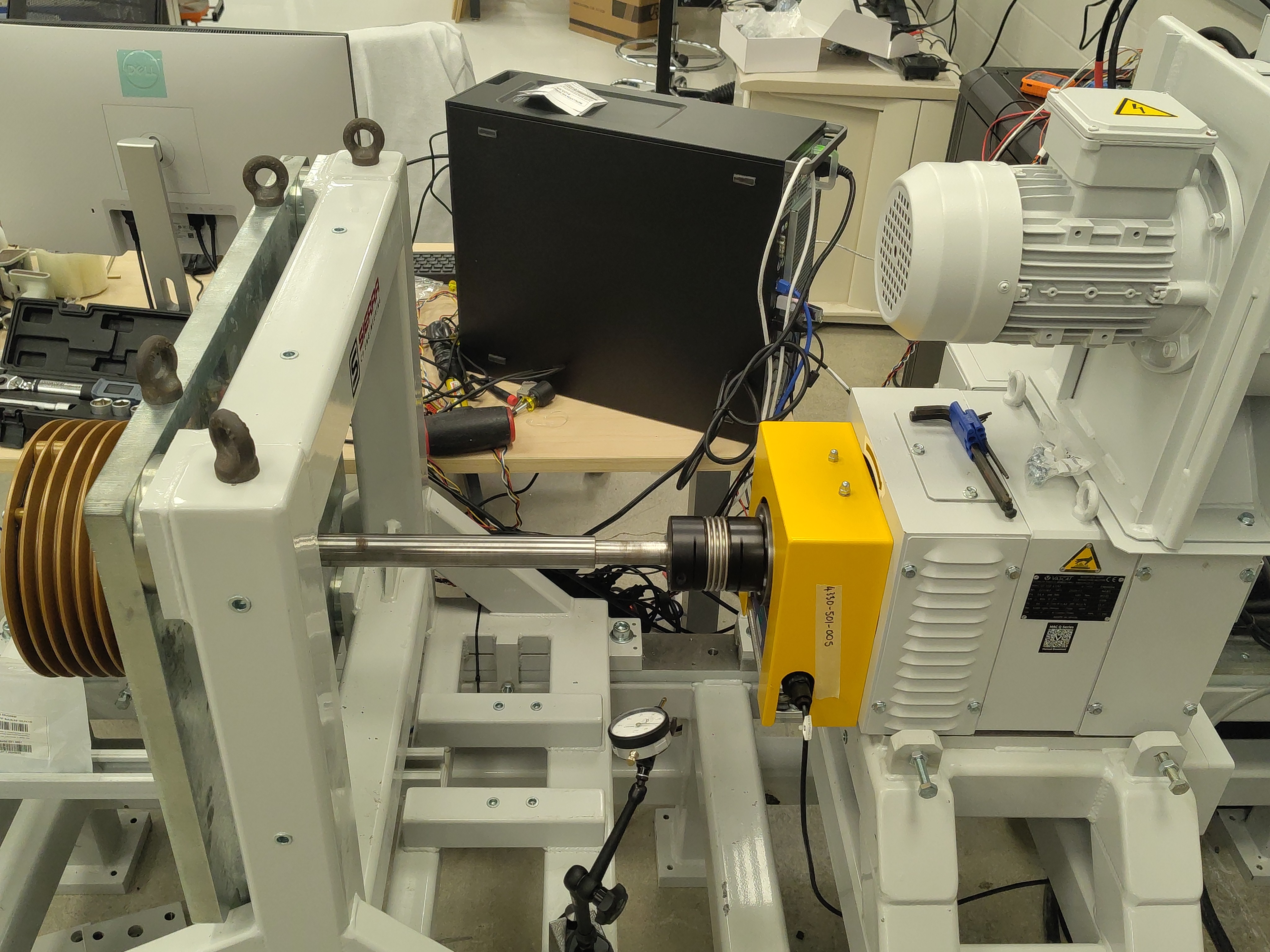
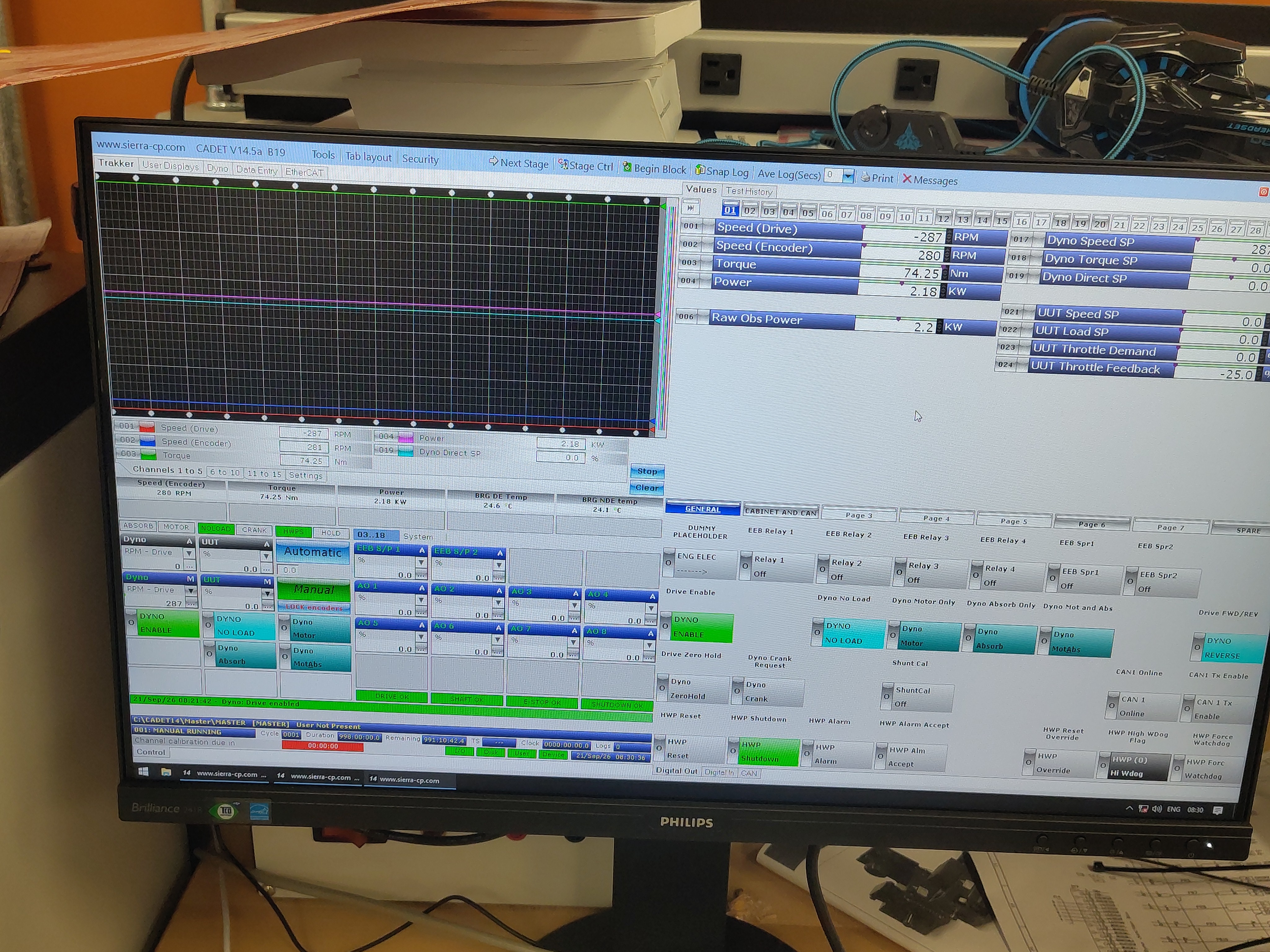
- Machine: 10-pole (5 pole-pair) 3-phase induction machine, shaft driven by the dynamometer through a torque flange (ATO-101-005) at ~280 RPM.
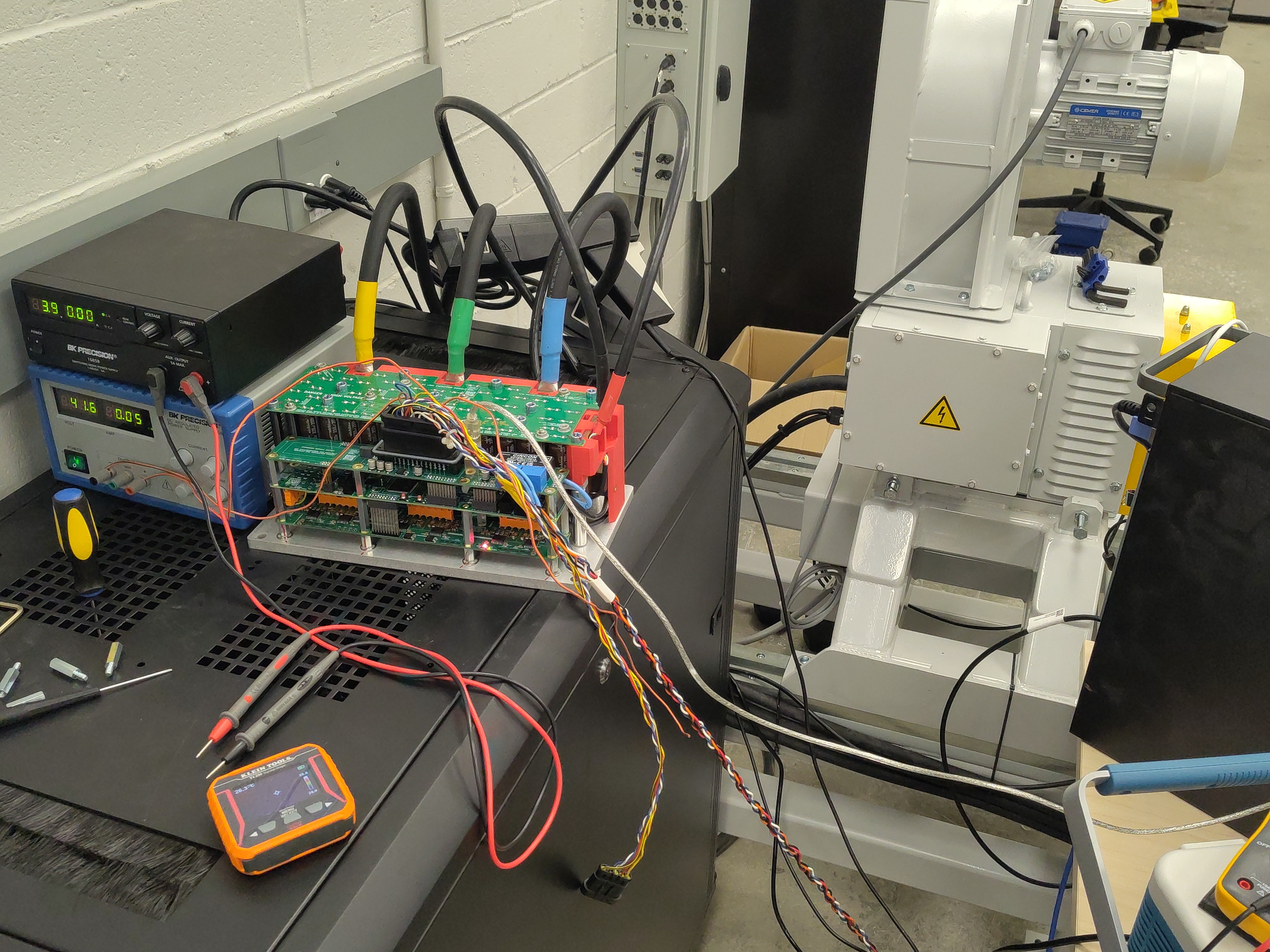
- DC supply: BK Precision bench supplies holding a ~52 VDC bus; regenerated energy returned to the bus/supply.
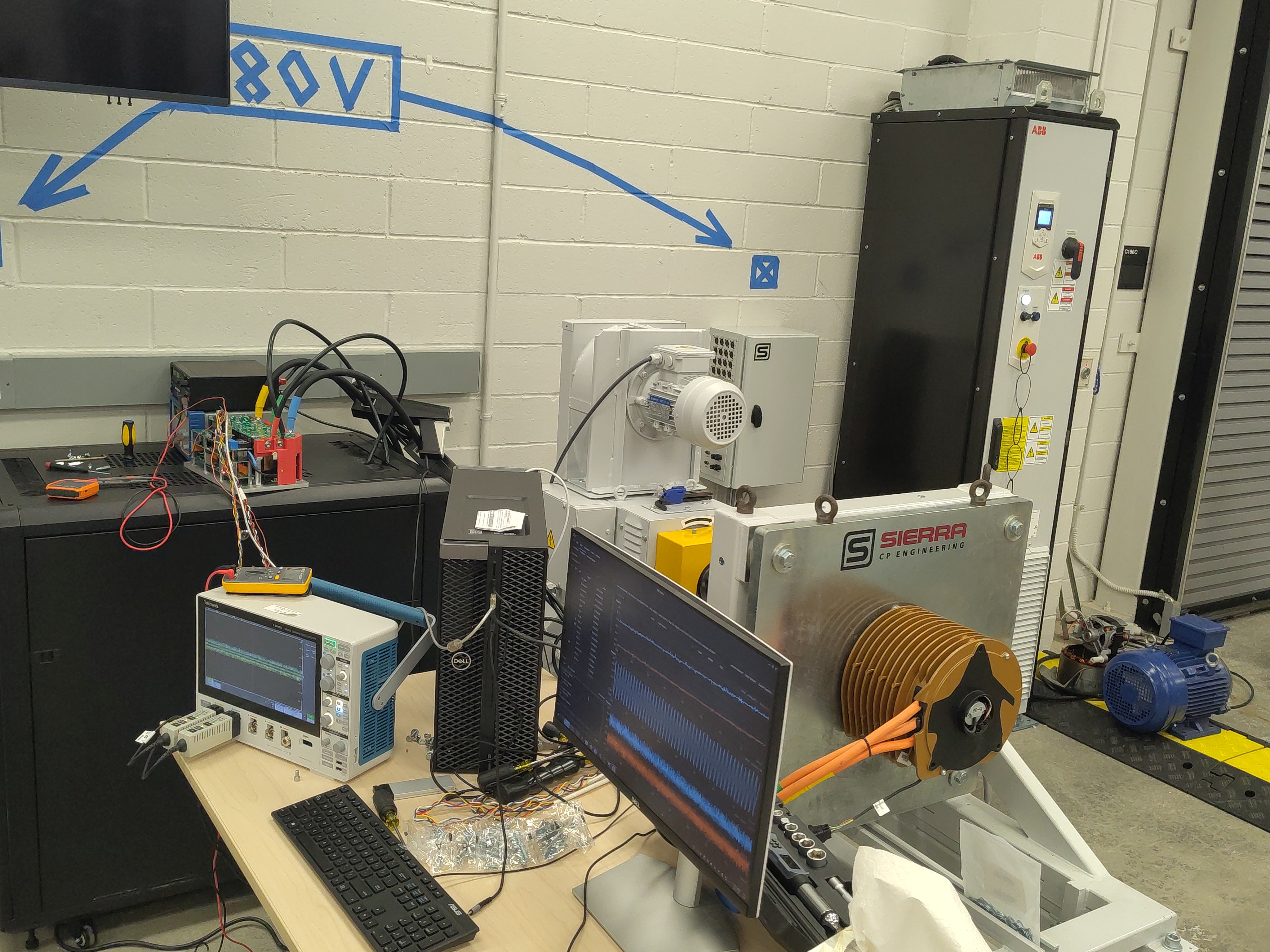
- Instrumentation: RTE Studio telemetry logged at ~14 Hz (19,463 samples), Klein Tools TI250 thermal imager, Tektronix 5 Series MSO, Sierra Trakkor dyno software.
Test conditions
| Parameter | Value |
|---|---|
| DC bus voltage | ~52 VDC (50.6–52.6 V observed) |
| Shaft speed | ~280 RPM (dynamometer-held; sagged to ~263 RPM at full regen torque) |
| Current command | Direct IqVar override, 0 → −10 → … → −100 A in 10 A steps, then hold |
| Hold at −100 A | 22.0 min (t = 35 s to 1355 s of the log) |
| Electrical power at 100 A | ~296 W average into the DC bus (~5.8 A DC-link) |
| Ambient temperature | ~23–27 °C |
| Cooling | None (open-air natural convection, bare stack) |
| Throttle inputs | 0 throughout (pure current override) |
Procedure
- Dynamometer spins the machine at ~286 RPM with the DUT enabled and
IqVar = 0(baseline, ~9 s). IqVarstepped −10 A per command to −100 A over ~25 s.- Held at −100 A for 22 minutes while telemetry and thermal images were captured.
- Released to
IqVar = 0; logging continued ~20 s into cooldown.
Electrical results
Per-step statistics from the full-rate telemetry log (Pdc = DC-link power, Idc = DC-link current):
| Iq command | Step duration | Avg Iq | Peak |phase| | Avg Pdc | Avg Idc |
|---|---|---|---|---|---|
| 0 (baseline) | 9.3 s | +0.1 A | 4 A | −30 W (supply feed) | −0.6 A |
| −10 A | 4.2 s | −9.9 A | 13 A | 23 W | 0.4 A |
| −20 A | 2.0 s | −19.0 A | 21 A | 69 W | 1.3 A |
| −30 A | 3.7 s | −32.8 A | 50 A | 108 W | 2.1 A |
| −40 A | 2.0 s | −35.3 A | 48 A | 149 W | 2.9 A |
| −50 A | 3.3 s | −50.0 A | 64 A | 171 W | 3.3 A |
| −60 A | 2.1 s | −55.3 A | 74 A | 200 W | 3.9 A |
| −70 A | 2.4 s | −68.7 A | 86 A | 238 W | 4.6 A |
| −80 A | 2.4 s | −81.6 A | 104 A | 264 W | 5.1 A |
| −90 A | 3.4 s | −90.3 A | 118 A | 279 W | 5.4 A |
| −100 A (hold) | 22.0 min | −100.0 A | 145 A | 299 W | 5.8 A |
During the 22-minute hold:
- Average q-axis current was −100.0 A with every one of the 16,628 settled samples below zero — continuous, uninterrupted regen.
- Instantaneous phase-current peaks reached ±145 A (100 A fundamental plus switching ripple and brief
idexcursions). - DC-link power averaged 299 W (max 381 W) at ~5.8 A; total regen energy over the hold was ≈390 kJ (≈108 Wh), ≈109 Wh for the whole run. This is the "low power" in the title: full phase current, but only ~0.3 kW because the bus is 52 V.
- Bus voltage stayed in a tight 50.6–52.6 V band with no sign of regeneration-induced overvoltage.
Thermal results
Board NTCs (inside the stack) climbed steadily and plateaued, with no runaway:
- Inverter temp 1: 33.4 °C → 79.1 °C (peak 79.4 °C) — about +46 K
- Inverter temp 2: 35.6 °C → 80.3 °C (peak 80.4 °C, reached seconds after release) — about +45 K
- After release, both sensors began cooling immediately (77.7 / 79.1 °C by the end of the log).
Thermal imager spot readings on the exterior (all taken during the −100 A hold):
Board, early in the hold (~7 min)
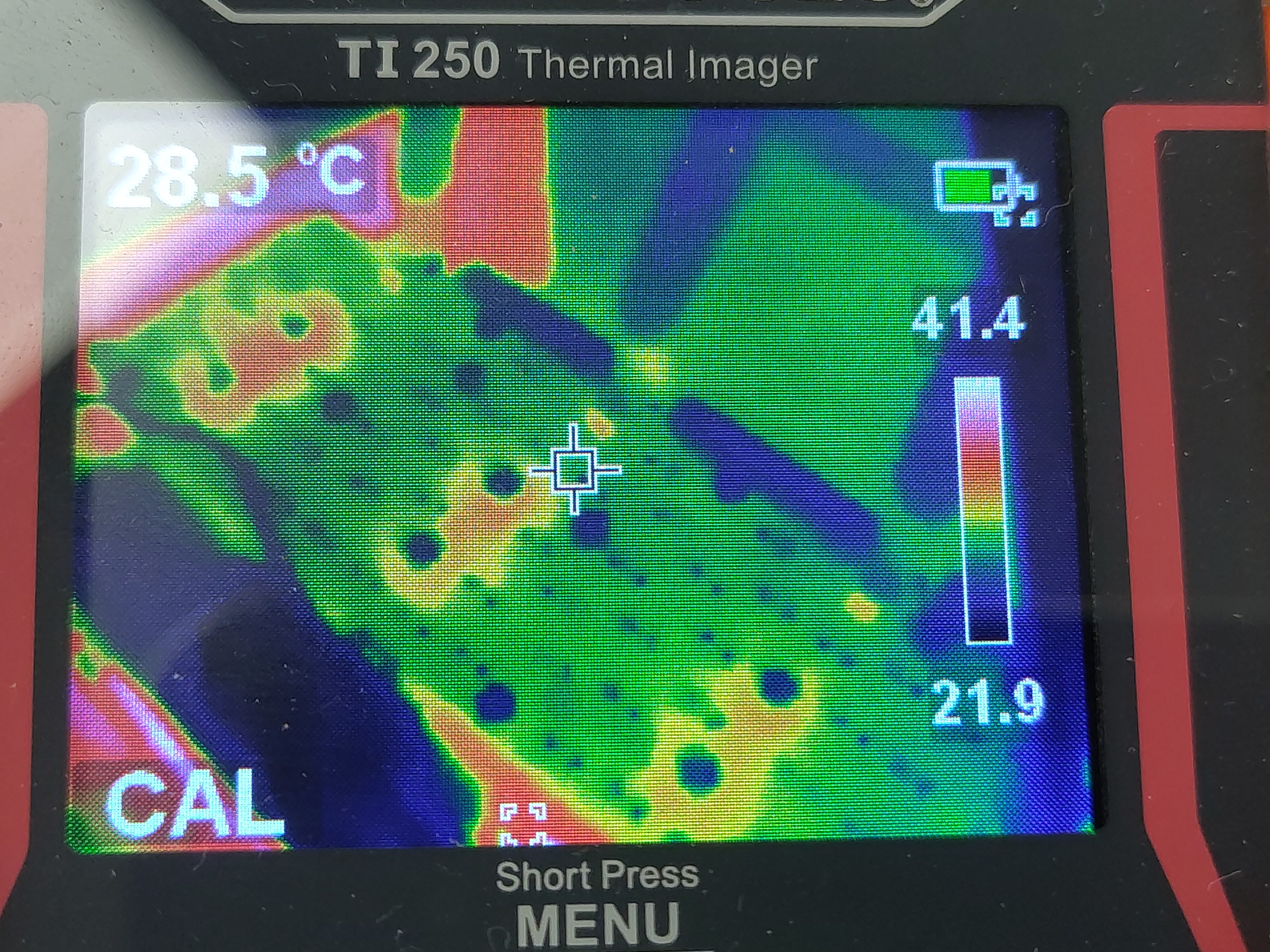
- Crosshair: 28.5 °C; imager span 21.9–41.4 °C.
DC-link capacitors, early (~7 min)
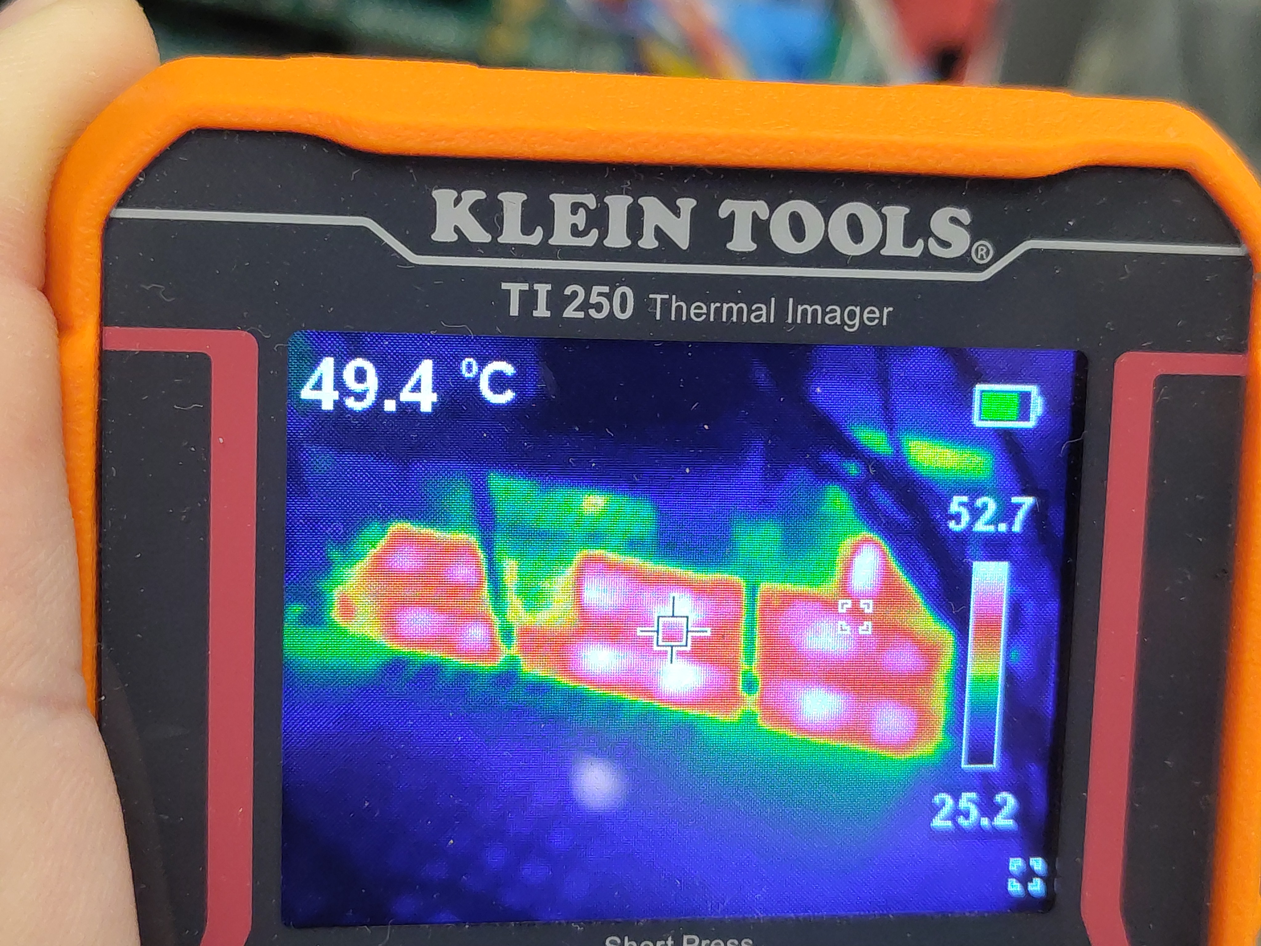
- Crosshair: 49.4 °C; max 52.7 °C.
DC-link capacitors (~8 min)
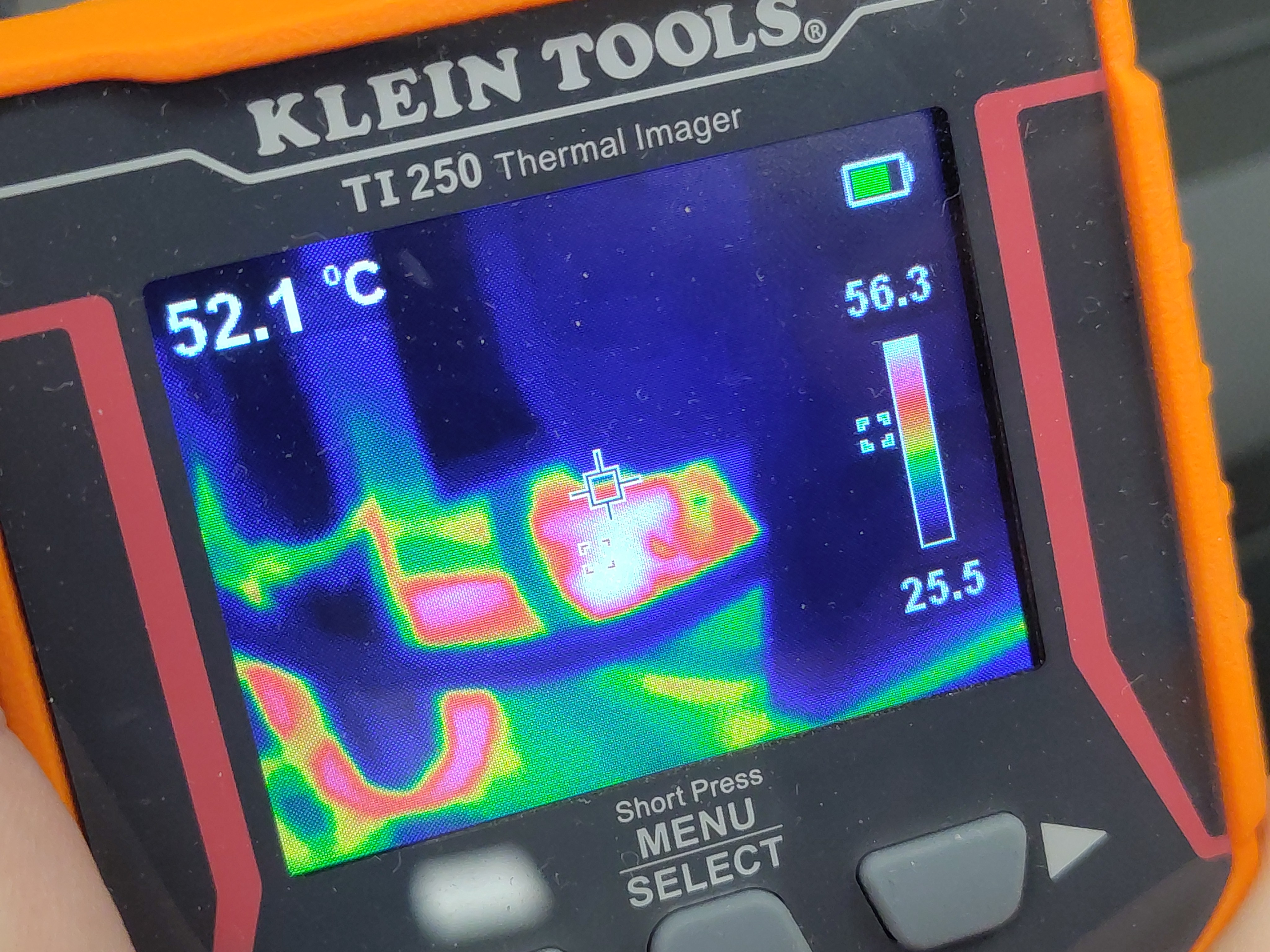
- Crosshair: 52.1 °C; max 56.3 °C.
Board, late in the hold (~18 min)
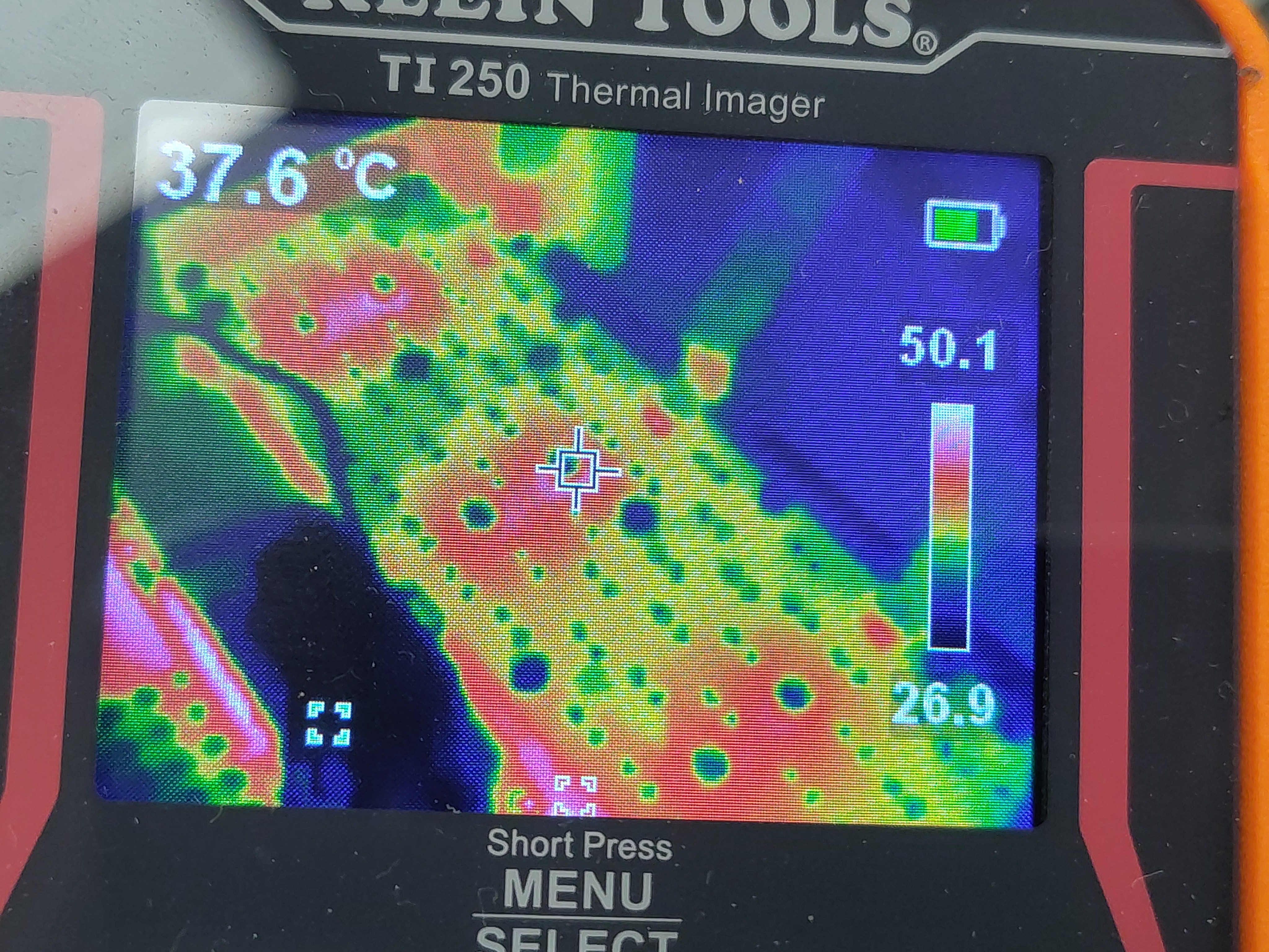
- Crosshair: 37.6 °C; max 50.1 °C.
Phase cabling / lugs, late (~18 min)
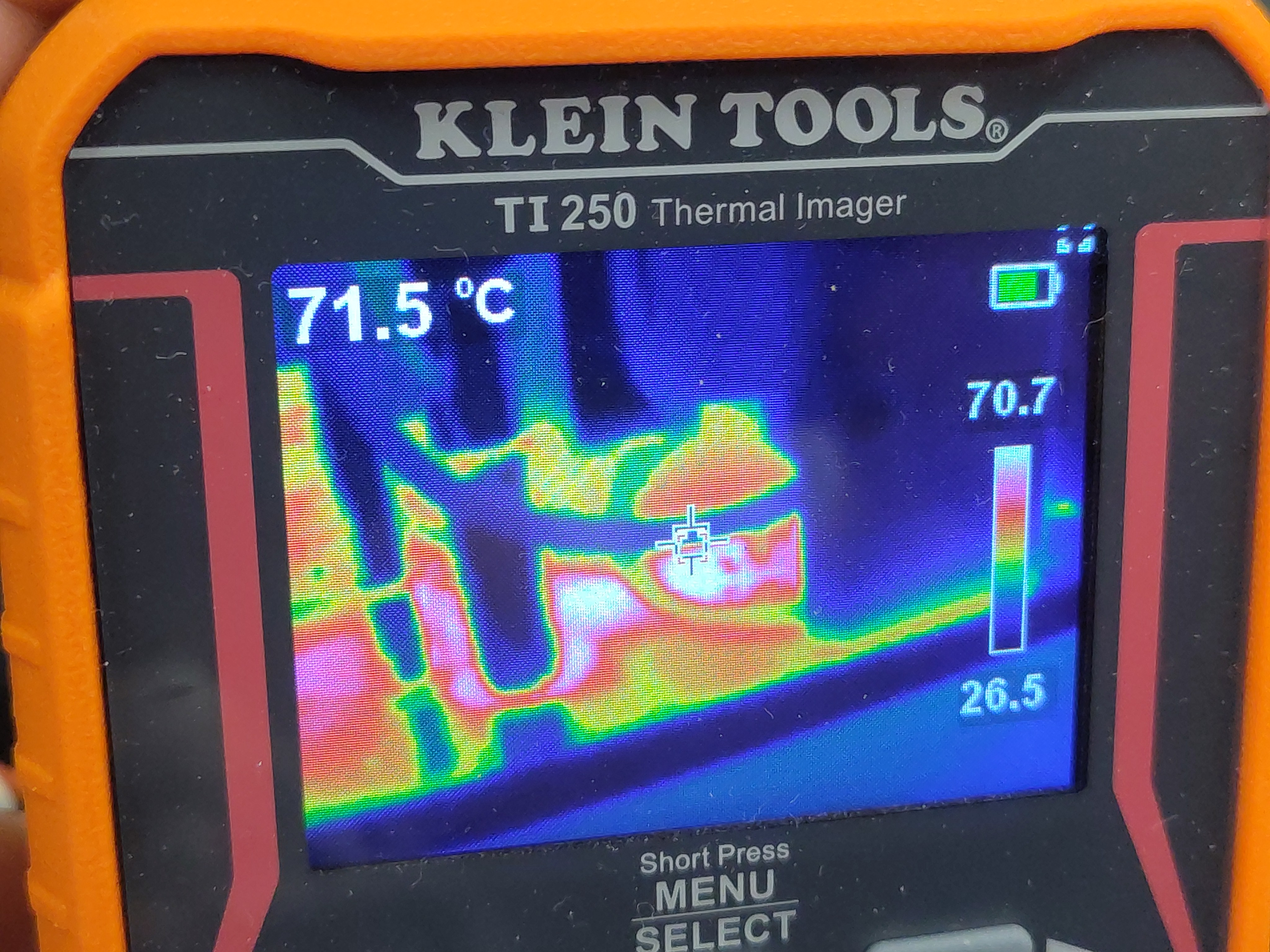
- Crosshair: 71.5 °C; max 70.7 °C scale top — the hottest exterior surface observed.
DC-link capacitors, late (~18 min)
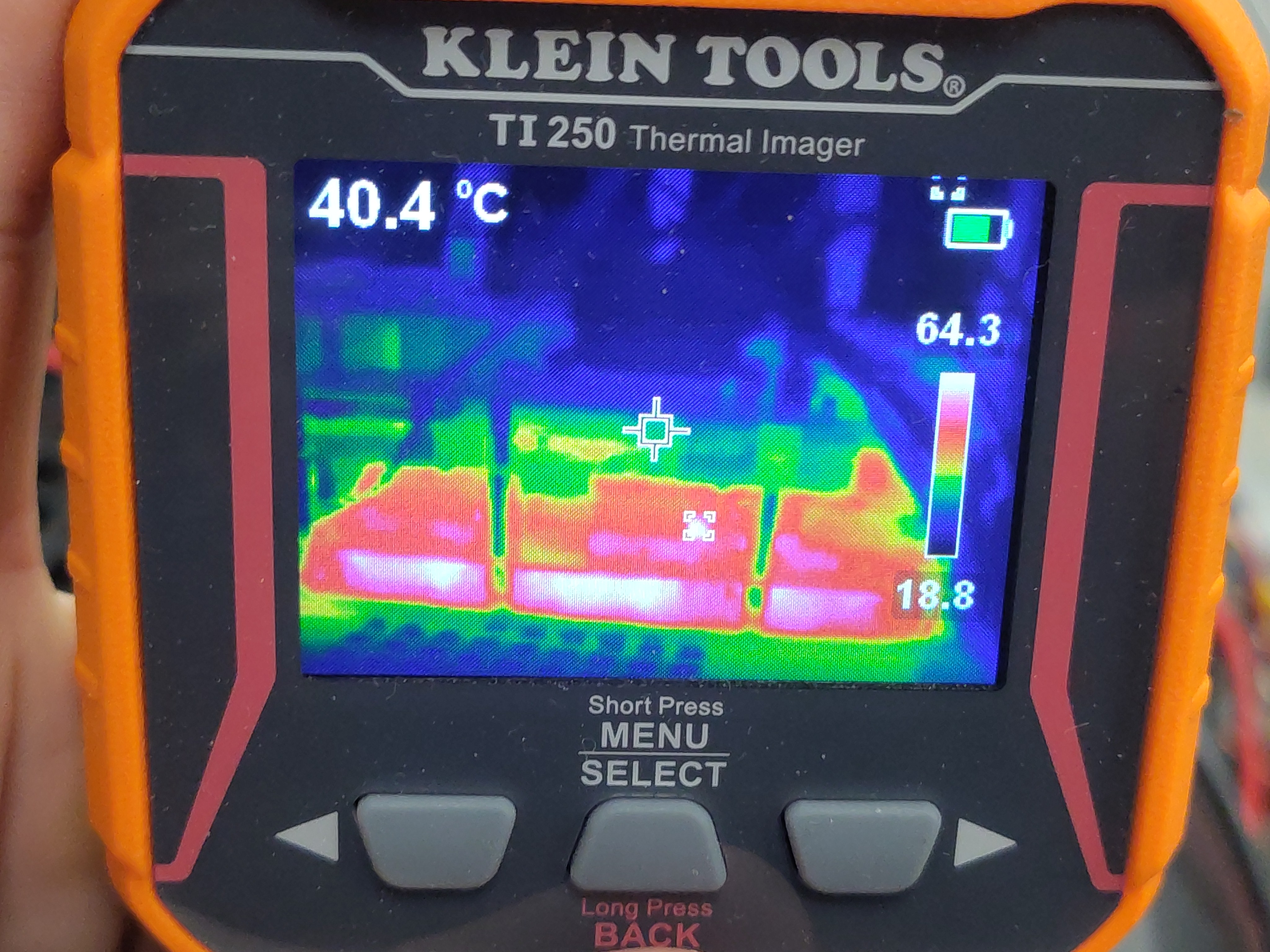
- Crosshair: 40.4 °C; max 64.3 °C along the capacitor bodies.
End state on the RTE Studio screen (~19 min)
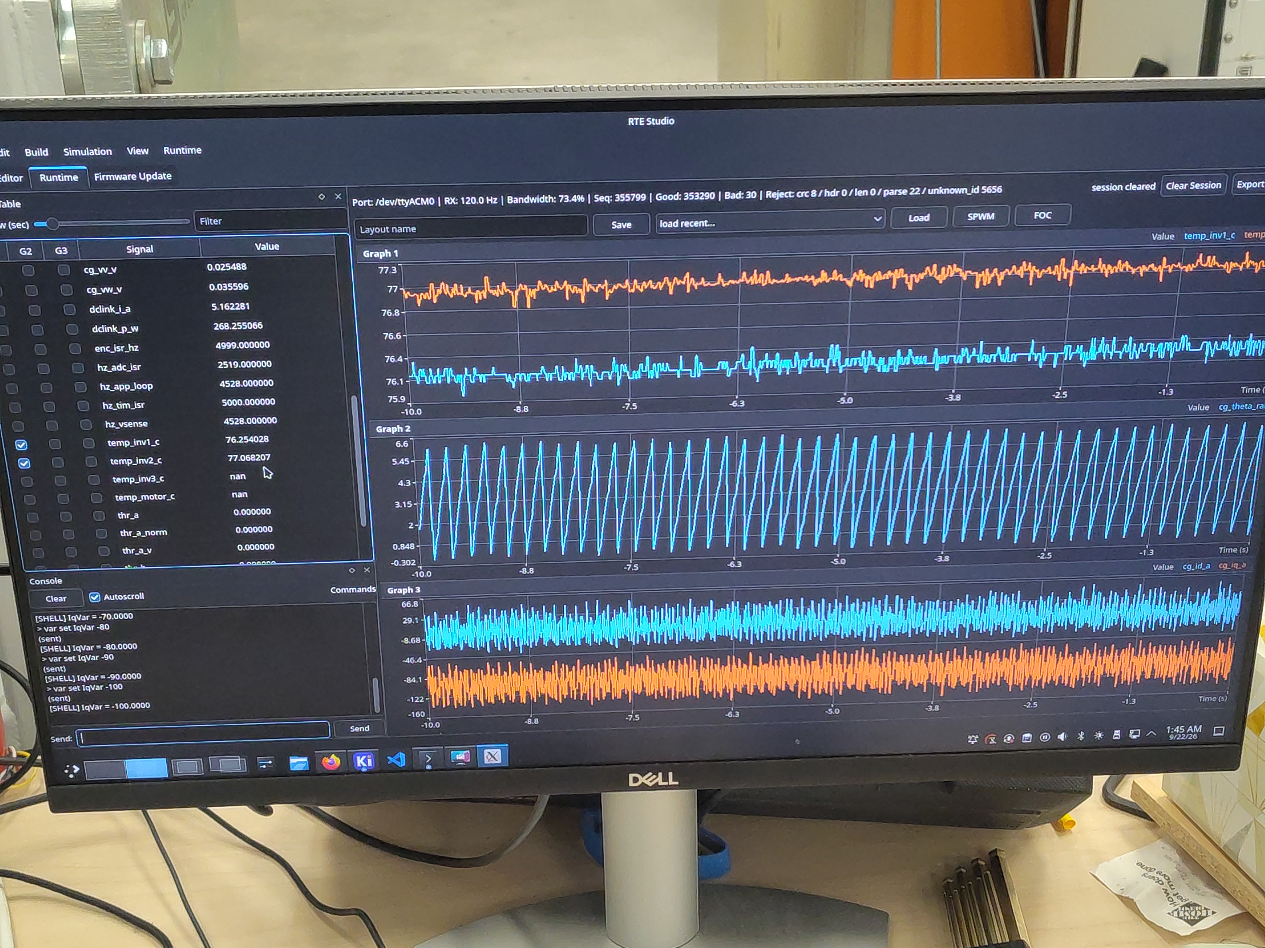
- Console history shows the final steps down to
IqVar = -100; live values read 76.3 / 77.1 °C board temps with 5.16 A / 268 W on the DC link — consistent with the logged data.
Telemetry overview
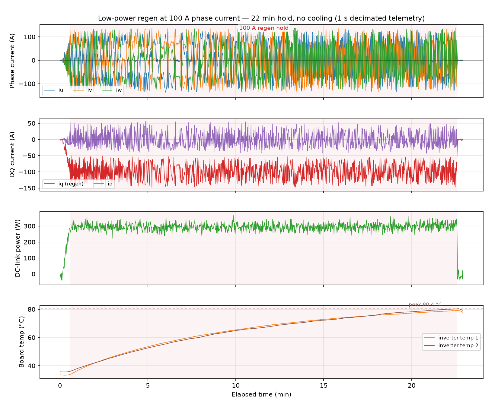
Open telemetry log: View the run in the Telemetry Viewer
Observations
- No faults, trips, or resets at any point; the current loop held −100 A for the full 22 minutes without intervention.
- This is deliberately a current stress, not a power stress: at 52 VDC the bus sees only ~6 A even at 100 A phase current. It verifies conduction paths, current sensing, and gate drive at rated phase current with essentially no cooling infrastructure.
- Machine-terminal power is not quoted for this run: P = (3/2)(vd·id + vq·iq) from this session's logged dq voltages does not reconcile with DC-link power — the implied ≈0.7 kW of inverter dissipation is inconsistent with a bare stack plateauing at 80.4 °C. The dq-voltage calculation reconciles in firmware build
855dbcee90d611cband is reported from the 400 A run onward. - Shaft speed sagged from ~280 to ~263 RPM as regen torque loaded the dynamometer's speed control.
- The
temp_inv3_candtemp_motor_cchannels were unpopulated (null) for this build. - Interior NTCs read ~10–15 °C above the hottest exterior imager spots — expected, as the sensors sit inside the stack next to the dissipating devices.
- Thermal imager readings are crosshair/spot values from an auto-scaled palette; treat them as ±2–3 °C.
Conclusion
Pass. The bare C2-class power stage sustained a 100 A regenerative phase current for 22 minutes with no cooling and no faults. Peak board temperature was 80.4 °C (≈+46 K over ambient start) with a clear plateau, and the hottest exterior point (phase lugs) reached ~71.5 °C. The power stage demonstrably tolerates rated phase current at low DC-bus voltage on natural convection alone, with comfortable thermal margin. This run complements the no-load and 180 V induction-motor bring-up tests by covering the high-current/low-voltage regen corner.
Artifacts
- Decimated telemetry log (JSONL, 1 s) - open in Telemetry Viewer
- Telemetry overview plot (PNG)
- Photos: DUT bare stack, bench, test cell, dyno coupling, dyno screen, RTE Studio end state
- Thermal images: board ~7 min, caps ~7 min, caps ~8 min, board ~18 min, cables ~18 min, caps ~18 min
Notes
- The full-rate log (19,463 samples, 16 MB) is retained alongside this report as
100a-regen-test.jsonl(not committed); the linked artifact is decimated to one sample per second for the repository. - Photo elapsed times assume the camera clock (UTC-7) matches the session wall clock; the telemetry session ran 08:26–08:49 UTC on 2026-09-22.
- The dyno screen photo shows the cell's Trakkor display (shaft speed ~280 RPM) for context; electrical values in this report are from the DUT's own telemetry unless stated.