14 · v0.1 · 2026-09-22Download PDF
| Doctype | Test Report |
|---|---|
| Product line | openvvvf |
| Applies to | openvvvf-control-module, chassis-size-2 |
| Version | 0.1 |
| Date | 2026-09-22 |
| Description | Continuation of the Gen7 size 2 200 A regenerative run after the baseplate NTC (TS2) reached 79 °C, covering the intended thermal OTP trip and recorded cooldown. |
| Test id | 14 |
| Nav order | 363 |
| Normative refs | OV-TEST-HW-INDEX, OV-TEST-HW-REGEN-200A-GEN7-SIZE2 |
Thermal OTP Trip — 200 A Regen, Gen7 Size 2
This report documents the intended thermal over-temperature protection (OTP) response in the Gen7 size 2 regenerative test. It covers the remaining telemetry after baseplate temperature sensor TS2 first reached 79 °C. The 200 A q-axis command remained active for another 36.1 seconds, then the controller entered FAULT with flags 0x04000000. Telemetry continues for approximately 28 seconds after the trip as the assembly cools.
This is the continuation of the same test recording analyzed in OV-TEST-HW-REGEN-200A-GEN7-SIZE2, not a new power cycle. The heatsink mounting had no thermal interface material and a contact gap because phase leads tilted it backward. The OTP response is the purpose of this segment; thermal conclusions remain specific to this assembly.
Test setup
- DUT: OpenVVVF Gen7 size 2 inverter hardware.
- Operating point at start of segment:
IqVar = 200 A; baseplate TS2 first reached 79.0 °C at source-log t = 619.492 s. - Cooling assembly: Heatsink installed without thermal interface material; phase-lead interference left a gap at the thermal interface.
- DC bus: Nominal 50 V supply setting; measured bus was approximately 58 V during the loaded segment.
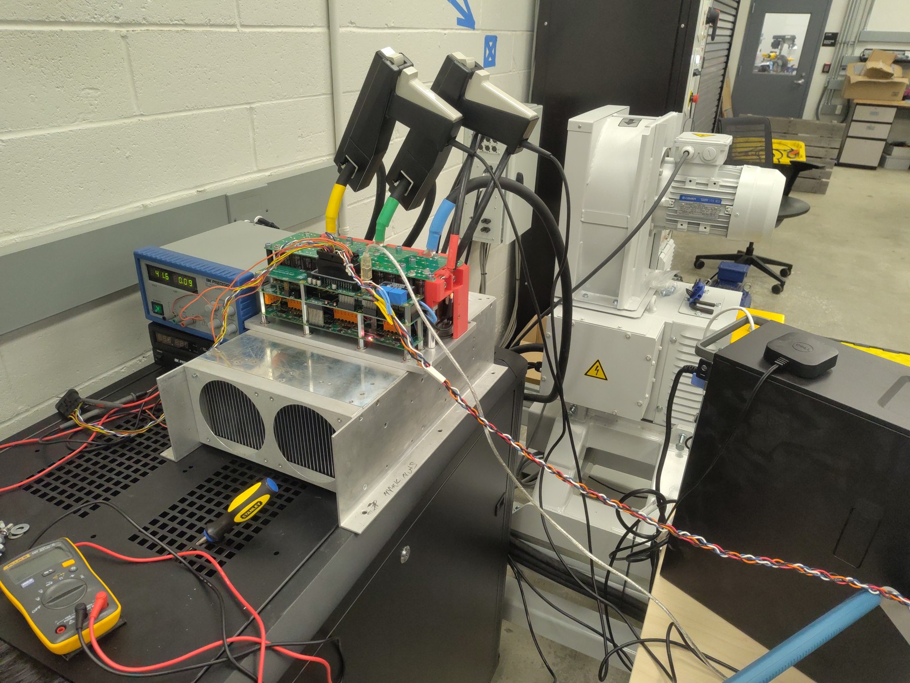
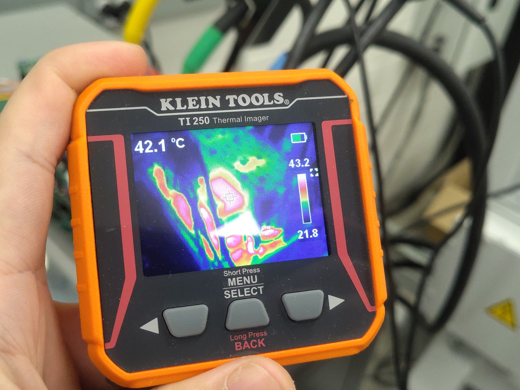
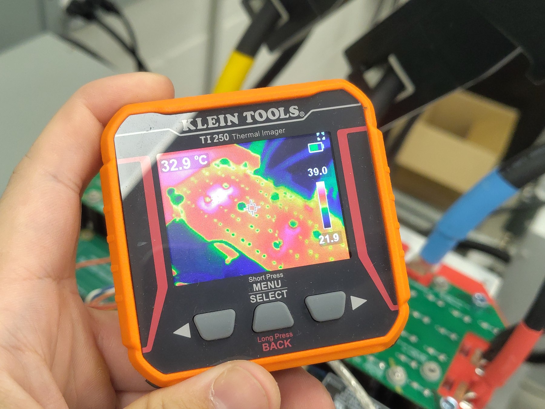
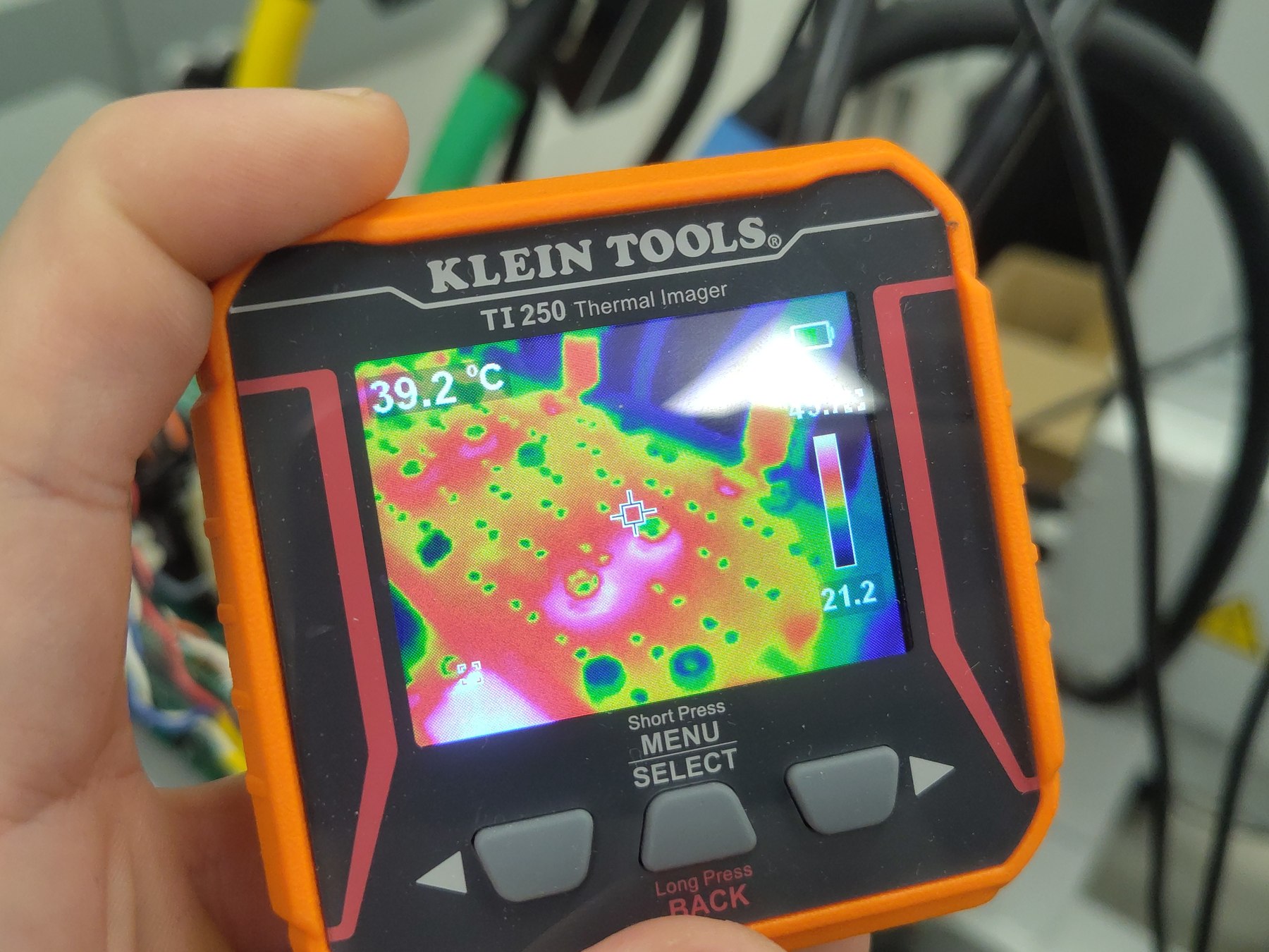
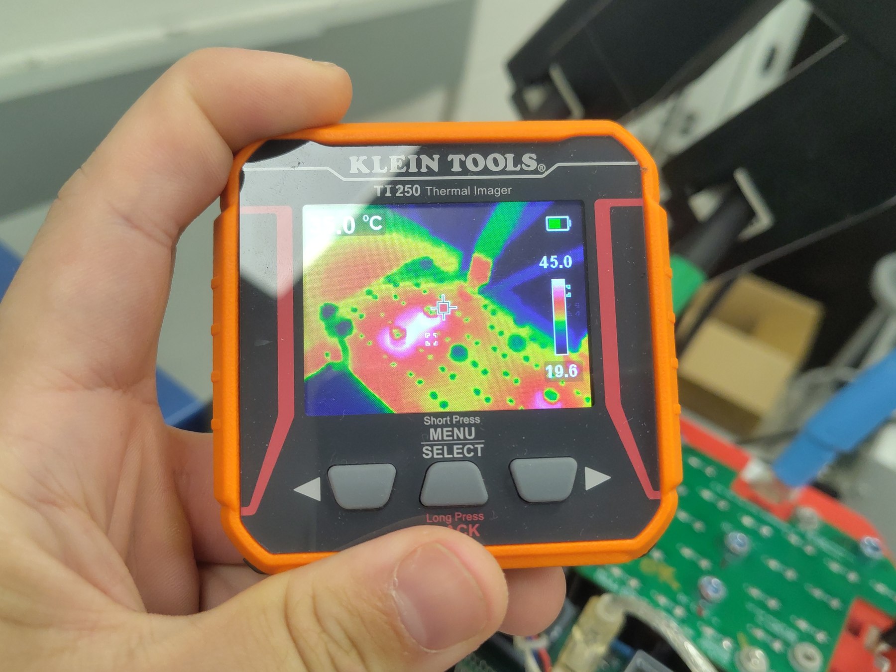
- Instrumentation: RTE Studio telemetry and Klein Tools TI250 thermal imager. Setup photographs and the source recording are included with the companion regen report.
Segment conditions
| Parameter | Value |
|---|---|
| Segment start | First temp_inv2_c (baseplate TS2) sample ≥79 °C, source t = 619.492 s |
| OTP trip | control_state = FAULT at t = 655.614 s |
| Time from 79 °C split to trip | 36.1 s |
| 200 A command duration before trip | 9 min 51 s total from command at t = 64.175 s |
| Average Iq from split to trip | 200.0 A |
| Average DC-link power from split to trip | 3.14 kW into the DC link |
| Logged OTP flag | 0x04000000 |
| Post-trip telemetry | Approximately 28.2 s |
Procedure and OTP response
- Continued from the 200 A regenerative run at the first logged 79 °C reading; no command change is recorded at the report split.
- Maintained the 200 A q-axis command while monitoring both baseplate NTC channels and DC-link telemetry.
- At t = 655.614 s, the controller transitioned from
RUNNINGtoFAULT, which the operator identified as the intended thermal OTP response. The next logged fault flags were0x04000000. - Retained the remainder of the session log to observe the post-trip state and temperature cooldown.
Across the 36.1 s from the 79 °C boundary to the fault, the telemetry averaged 200.0 A q-axis current, 3.14 kW DC-link power, and 54.1 A DC-link current. The measured bus averaged 58.0 V and remained between 57.2 V and 58.9 V during this loaded segment.
Thermal results
At the 79 °C analysis boundary, baseplate TS1 (temp_inv1_c) was 76.7 °C and baseplate TS2 (temp_inv2_c) was 79.0 °C. The highest logged temp_inv2_c before the controller fault was 80.0 °C at t = 655.152 s, about 0.46 s before the fault-state transition. The last sample before the transition read 77.7 °C and 79.9 °C on baseplate temperature channels TS1 and TS2 respectively. TS1 peaked at 77.7 °C before the transition.
Following the OTP transition, the reported temperatures fell. By the end of the session at t = 683.785 s, readings were 72.2 °C and 74.5 °C. The logged DC bus dropped sharply during the fault transition (minimum 23.3 V in the post-trip interval) and was 49.7 V at the end of the recording; the bus transient is recorded here as observed, not characterized as a separate acceptance criterion.
Telemetry overview
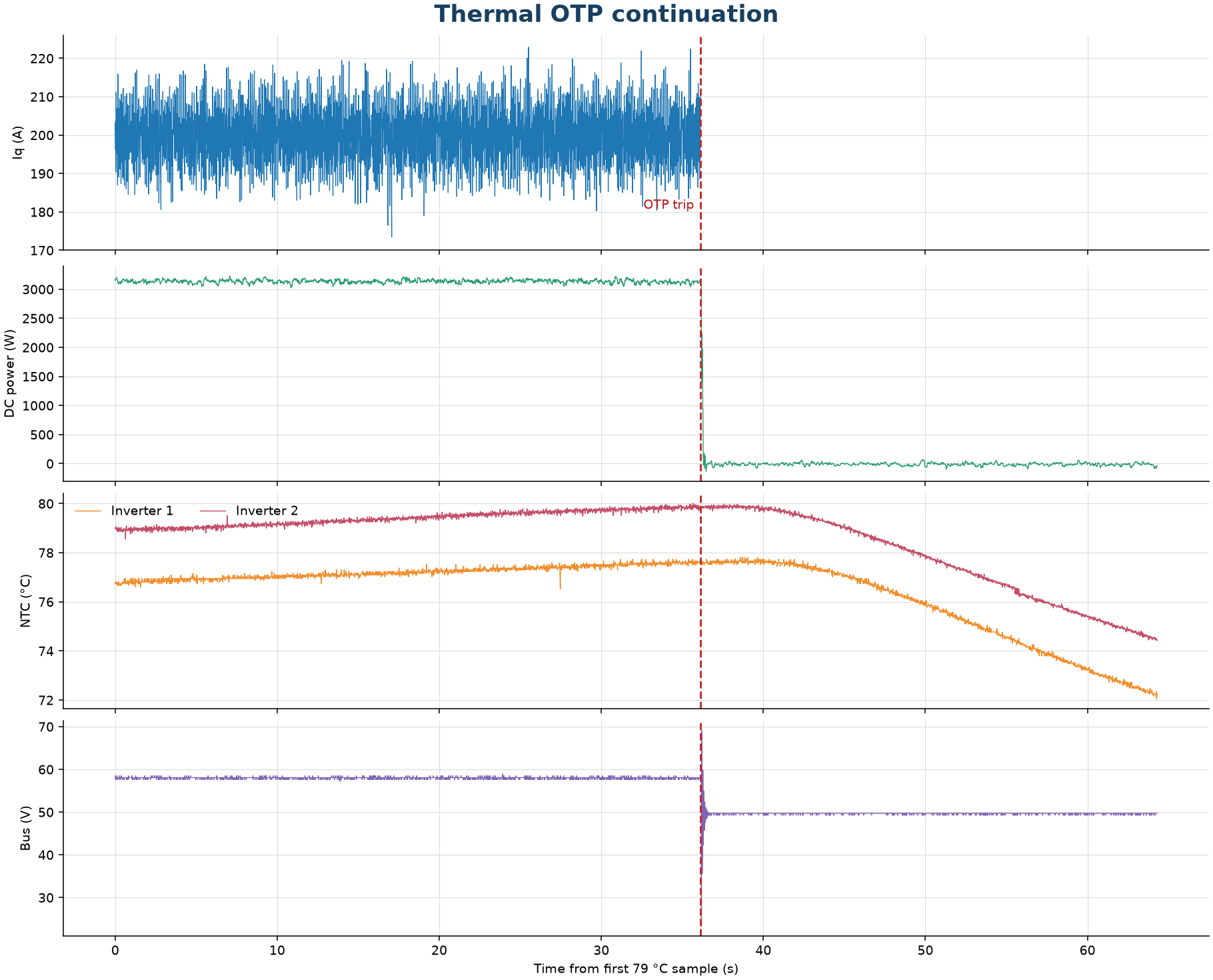
Open continuation telemetry: View the OTP segment in the Telemetry Viewer
Observations
- The intended thermal OTP response occurred: the controller entered
FAULTwhile the 200 A regenerative command was active, with the operator-identified OTP flag0x04000000. - The trip occurred 36.1 s after the first
temp_inv2_csample at or above 79 °C and 9 min 51 s after the 200 A command was issued. - Baseplate TS2 (
temp_inv2_c) reached 80.0 °C shortly before the state transition; TS1 peaked at 77.7 °C. - The telemetry confirms the test reached its planned protective endpoint. It does not establish heatsink cooling performance because the heatsink lacked interface material and was separated by a gap.
- After the fault, the exported
cg_iq_achannel holds a fixed value; the telemetry plot stops that trace at the fault marker and uses the continuing power, voltage, and temperature channels for cooldown. - The recorded DC-link voltage transient at the fault transition is retained for follow-up review.
Conclusion
Pass for thermal OTP response. After the 200 A regenerative run reached 79 °C, the controller entered its intended thermal OTP fault state 36.1 seconds later with flag 0x04000000. The log shows the temperatures decreasing during the post-trip interval. Because the heatsink had a gap and no thermal interface material, the trip temperature and heating rate apply only to this test assembly and should not be treated as a validated heatsink result.
Artifacts
- Full-rate OTP continuation telemetry (JSONL) — open in Telemetry Viewer
- OTP telemetry overview plot
- Full source log: 200 A telemetry
- Setup and thermal photographs: dynamometer view, TI250 view 1, TI250 view 2, TI250 view 3, TI250 view 4
- Dynamometer setup video