
16 · v0.2 · 2026-09-23Download PDF
| Doctype | Test Report |
|---|---|
| Product line | openvvvf |
| Applies to | openvvvf-control-module, chassis-size-2 |
| Version | 0.2 |
| Date | 2026-09-23 |
| Description | Gen7 size 2 regenerative run at 2,000 RPM shaft speed stepping to a 450 A q-axis command with a Chroma load bank clamping the bus at 150 V, returning about 13 kW to the DC link. Sustained 78 s at 450 A until the inverter overtemperature protection tripped at about 80 °C baseplate during the commanded stop, matching the behavior in the 200 A OTP report. Also resolves the 400 A report's unexplained phase-current spikes as Tektronix current-clamp (150 A rated) saturation. |
| Test id | 16 |
| Nav order | 365 |
| Normative refs | OV-TEST-HW-INDEX, OV-TEST-HW-REGEN-400A-GEN7-SIZE2, OV-TEST-HW-THERMAL-OTP-200A-GEN7-SIZE2 |
450 A / 13 kW Regen — Gen7 Size 2
This report continues the Gen7 size 2 high-current regen series that started with OV-TEST-HW-REGEN-400A-GEN7-SIZE2, using the same bench: Sorensen supply (regenerative sink limited to ~50 A) with a Chroma DC electronic load bank in constant-voltage mode at 150 V across the DC link. The machine was spun faster this time — approximately 2,000 RPM shaft speed versus ~1,470 RPM in the 400 A run — so each amp of q-axis current returned more power. After a rapid staircase the inverter held a 450 A q-axis command for 77.7 s, returning 12.8 kW on average (13.4 kW peak) to the DC link, until the inverter overtemperature protection tripped at ~80 °C baseplate partway through the commanded stop. The trip matches the intended protection behavior documented in OV-TEST-HW-THERMAL-OTP-200A-GEN7-SIZE2.
This run also closes the open item from the 400 A report: the phase-current "spikes" seen on the oscilloscope there were the Tektronix current clamps saturating — they are rated at 150 A, not the 400–450 A being measured — a measurement artifact, not an inverter anomaly.
Test setup
- DUT: OpenVVVF Gen7 size 2 inverter hardware, firmware
foc_demograph (hash855dbcee90d611cb, same build as the 400 A run). - Machine: Induction machine coupled to a Sierra CP Engineering dynamometer at approximately −2,000 RPM mechanical during the staircase and hold.
- DC supply: Sorensen bench supply (regenerative sink limited to ~50 A) in parallel with a Chroma DC electronic load bank in constant-voltage mode at 150 V across the DC link. The supply held ~145 V on the bus at low regen current, so the Chroma clamp engaged from roughly the 300 A step onward.
- Instrumentation: RTE Studio telemetry (all quoted currents and powers are inverter telemetry, not the clamp channel). No bench photographs were taken this session; bench and instrument photos from the identical setup are in the 400 A report.
- Temperature channels: baseplate NTCs TS1 (
temp_inv1_c) and TS2 (temp_inv2_c); TS3 (temp_inv3_c) was not enabled (wiring defect, unrelated to the test).
Test conditions
| Parameter | Value |
|---|---|
| Hardware | Gen7 size 2, firmware foc_demo hash 855dbcee90d611cb |
| Machine speed | ~−2,000 RPM mech (vs ~−1,470 RPM in the 400 A run) |
| Bus at low current | ~145 V (supply setpoint; vs ~74 V in the 400 A run) |
| Bus clamp | Chroma CV at 150 V; 148.7–153.5 V from the 300 A step onward |
| Current command | IqVar staircase 25 → 200 A, then 300/400/450 A |
| Time at 450 A | 77.7 s commanded hold; OT trip 79.8 s after the 450 A command |
| Peak phase current | 470 A |
| Peak / average DC-link power | 13.4 kW / 12.8 kW during the 450 A hold |
| Regen energy into DC link | ≈0.283 kWh to the trip |
| Machine terminal real power P | −13.41 kW mean during the 450 A hold (generating; calculated from logged cg_vd_v/cg_vq_v/cg_id_a/cg_iq_a) |
| Machine reactive power Q | ≈7.2 kvar mean (machine magnetizing demand; quoted as magnitude — sign follows the logged dq frame) |
| Machine apparent power |S| | 15.23 kVA mean |
| Power factor (calculated) | 0.881 during the hold |
| Inverter efficiency (calculated) | ≈95% (12.80 kW DC-link ÷ 13.41 kW machine-terminal) |
| Baseplate NTC at trip | TS1 80.1 °C, TS2 75.5 °C (peak logged 81.2 / 76.5 °C, post-trip lag) |
| OT trip | FAULT at t = 164.3 s, flags 0x04000000 (OvertemperatureInverter), during the slew-limited stop |
Procedure
- Pre-charged and enabled the inverter; the dynamometer held the coupled machine at ~2,000 RPM.
- Stepped
IqVar25 → 200 A, then 300/400/450 A with short dwells. The bus rode the ~145 V supply until regen exceeded its sink capability, then the Chroma clamp held 150 V from ~300 A onward. - Held the 450 A command while logging telemetry and watching the baseplate NTCs. TS1 rose at ~0.6 °C/s through the hold.
- With TS1 at ~79.5 °C, commanded
IqVar 0. Temperature continued rising through the slew-limited decay, and the overtemperature protection tripped ~2.3 s into the stop at TS1 = 80.1 °C, cutting the current immediately. Telemetry continued through the ~2-minute cooldown.
Electrical results
Per-command statistics from the full-rate telemetry log (Pdc = DC-link power, Idc = DC-link current). Short segments average below their command because the slew-limited ramp occupies most of the window:
| Iq command | Step duration | Avg Iq | Peak phase current | Avg Pdc | Avg Idc |
|---|---|---|---|---|---|
| 25 A | 6.3 s | 23.9 A | 42 A | 872 W | 6 A |
| 50 A | 2.9 s | 49.7 A | 59 A | 1.68 kW | 12 A |
| 75 A | 2.4 s | 71.7 A | 83 A | 2.39 kW | 17 A |
| 100 A | 1.6 s | 95.3 A | 109 A | 3.12 kW | 22 A |
| 150 A | 1.8 s | 134.7 A | 163 A | 4.37 kW | 30 A |
| 200 A | 3.7 s | 192.3 A | 211 A | 6.70 kW | 46 A |
| 300 A | 3.9 s | 272.4 A | 311 A | 8.81 kW | 59 A |
| 400 A | 1.9 s | 344.5 A | 391 A | 10.54 kW | 69 A |
| 450 A hold | 77.7 s | 449.6 A | 470 A | 12.80 kW | 85 A |
At 2,000 RPM the back-EMF is higher than in the 400 A run, so the same 150 V clamp accepted ~85 A of DC-link current instead of ~56 A — that is where the 13 kW came from. Current control remained clean throughout: cg_vlimit_scale = 1.000 for the entire session (all clamping external), raw and filtered Iq tracked, and no gate faults occurred. The only fault was the overtemperature trip itself.
- Machine-terminal power (calculated): from the logged dq quantities (peak-amplitude convention, P = (3/2)(vd·id + vq·iq), Q = (3/2)(vq·id − vd·iq)), the machine delivered 13.41 kW mean during the hold while drawing ≈7.2 kvar of magnetizing reactive power (quoted as magnitude) — 15.23 kVA, power factor ≈ 0.881. The 0.61 kW between machine output and the 12.80 kW reaching the DC link is the inverter's own dissipation — calculated inverter efficiency ≈ 95% — which is exactly what drove the dry-mounted baseplate to the 80 °C trip in 78 s.
Thermal results and OT trip
Baseplate temperatures rose steeply under 13 kW with no thermal interface work (the assembly was still the dry-mounted setup of the previous sessions):
- Baseplate TS1 (
temp_inv1_c): 30.6 °C at the start of the staircase, 33.2 °C when the 450 A command was issued, 80.1 °C at the fault transition — a ~0.58 °C/s rise through the hold. Post-trip peak 81.2 °C at t ≈ 168 s (thermal lag). - Baseplate TS2 (
temp_inv2_c): 33.4 °C at start, 75.5 °C at the trip; post-trip peak 76.5 °C. - The controller entered
FAULTwith flags0x04000000(OvertemperatureInverter) at t = 164.33 s, 79.8 s after the 450 A command and ~2.3 s after the stop command. This is the same flag and threshold region as the 200 A OTP demonstration (trip at 80.0 °C logged), i.e. intended protective behavior rather than a malfunction. - After the trip the gates disabled immediately (no slew — the fault path cuts current at once) and both channels cooled to ~49–51 °C by the end of logging.
Resolution of the 400 A current-spike observation
The 400 A report closed with an unexplained oscilloscope observation: narrow repetitive spikes on the phase-current traces during the 400 A holds. The cause is now identified as measurement artifact — the Tektronix current clamps are rated at 150 A and clipped/saturated at the 400 A phase currents, distorting the traces. The inverter's own telemetry in that run showed no anomaly, which is consistent with this conclusion. The spikes should not be treated as a hardware finding; no further investigation of the inverter is required on that count.
Telemetry overview
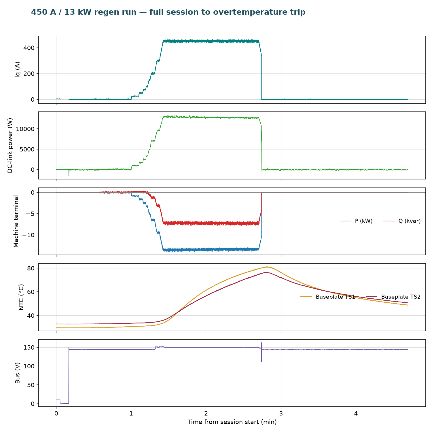
Open full session: View the run in the Telemetry Viewer
Observations
- Raising shaft speed to 2,000 RPM lifted regen power at the same 150 V clamp from 8.8 kW (400 A run) to 13 kW — DC-link current scales with available mechanical power, not with the clamp voltage alone.
- The Chroma clamp plus ~145 V supply setpoint meant the clamp engaged from ~300 A onward, earlier in the staircase than in the 400 A run.
- The overtemperature protection tripped during a commanded stop because the slew-limited decay (~50 A/s) leaves hundreds of amps flowing for seconds while the baseplate is still heating. Stopping earlier is the lever — the protection itself worked as designed.
- This session predates the thermal-paste rework of the power stage. The pasted assembly was subsequently validated at 200 A steady state — baseplate plateau 44.4 / 44.0 °C against 22.5 °C ambient — in OV-TEST-HW-REGEN-200A-STEADY-STATE-GEN7-SIZE2.
Conclusion
Pass. Gen7 size 2 hardware sustained a 450 A q-axis regen command at 2,000 RPM — 470 A peak phase current, 12.8 kW average / 13.4 kW peak returned to the DC link, ≈0.283 kWh over 78 s — with no control or gate faults, until the inverter overtemperature protection tripped at 80.1 °C baseplate, duplicating the intended protection behavior of the 200 A OTP report. The open phase-spike observation from the 400 A report is resolved as current-clamp saturation (150 A-rated probes at 400 A), a measurement artifact. Further high-current regen sessions should use appropriately rated current measurement and the thermally-pasted assembly.
Artifacts
- Decimated telemetry log (JSONL, 1 sample/s) — open in Telemetry Viewer
- Telemetry overview plot
- Full source telemetry log, retained for traceability