
13 · v0.3 · 2026-09-22Download PDF
| Doctype | Test Report |
|---|---|
| Product line | openvvvf |
| Applies to | openvvvf-control-module, chassis-size-2 |
| Version | 0.3 |
| Date | 2026-09-22 |
| Description | Gen7 size 2 regenerative run at a nominal 50 V bus and 200 A q-axis command, analyzed through the first 79 °C baseplate NTC (TS2) reading with heatsink contact gap and no thermal interface material. |
| Test id | 13 |
| Nav order | 362 |
| Normative refs | OV-TEST-HW-INDEX |
200 A Regen to 79 °C — Gen7 Size 2
This report covers the first portion of a regenerative dynamometer run on Gen7 size 2 hardware. The inverter was commanded in 25 A steps to 200 A q-axis current, then held there until baseplate temperature sensor TS2 (temp_inv2_c) first reached 79 °C. The selected analysis interval ends at t = 619.492 s, 9 min 15 s after the 200 A command. Over the 200 A hold to that point, the logged DC link received about 3.14 kW on average, or approximately 0.485 kWh total.
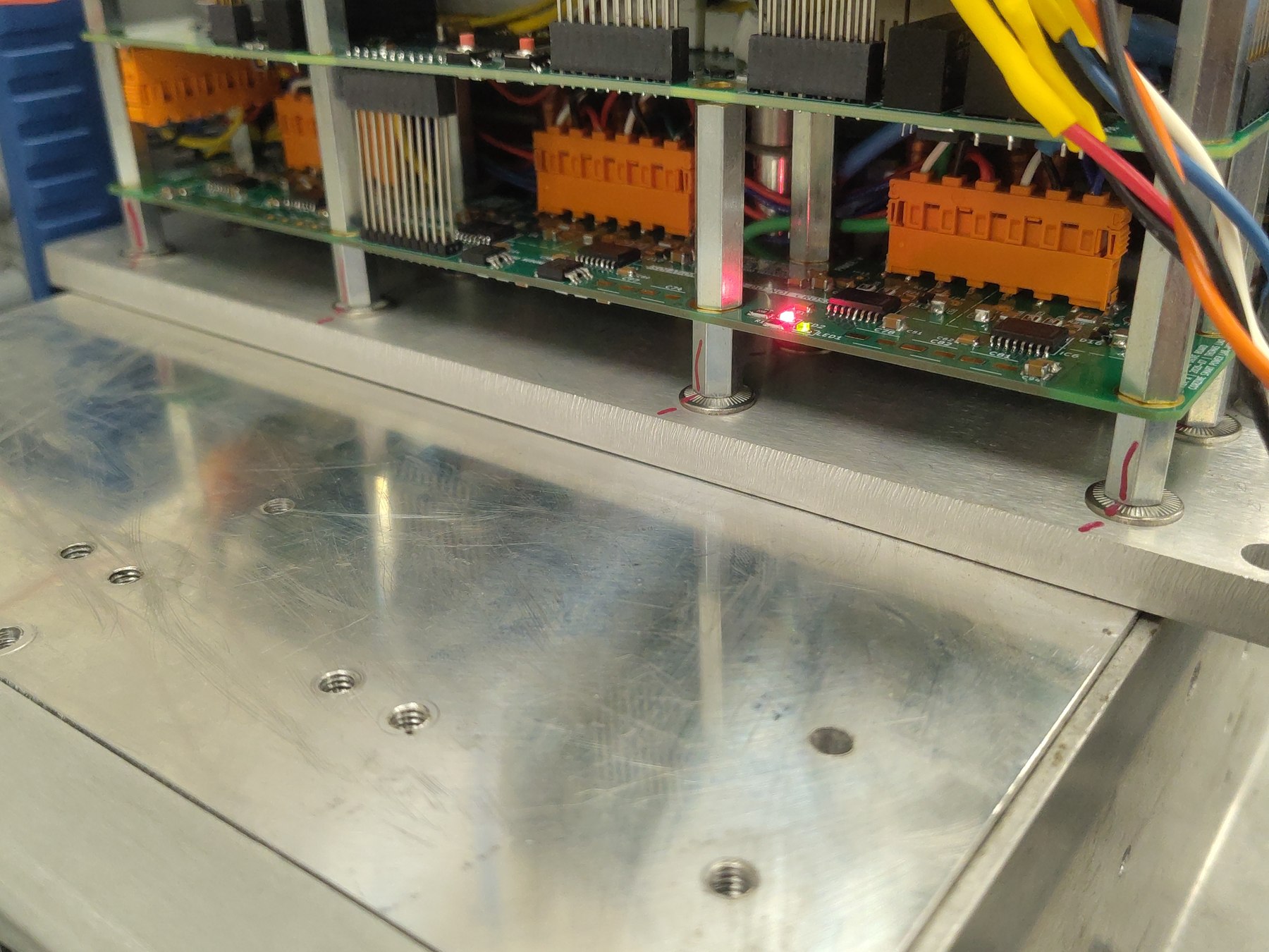
A heatsink was fitted for this run, unlike the 100 A test, but no thermal interface material was used. The phase leads tilted the heatsink backward and left a gap at the thermal interface. The temperatures here describe that as-tested assembly and do not establish heatsink performance with correct contact.
Telemetry boundary: The 79 °C sample is the report split point. The source log does not show the 200 A command being removed at that instant; it continues into the thermal OTP event documented in OV-TEST-HW-THERMAL-OTP-200A-GEN7-SIZE2. The two reports are separate analyses of that continuous recording.
Test setup
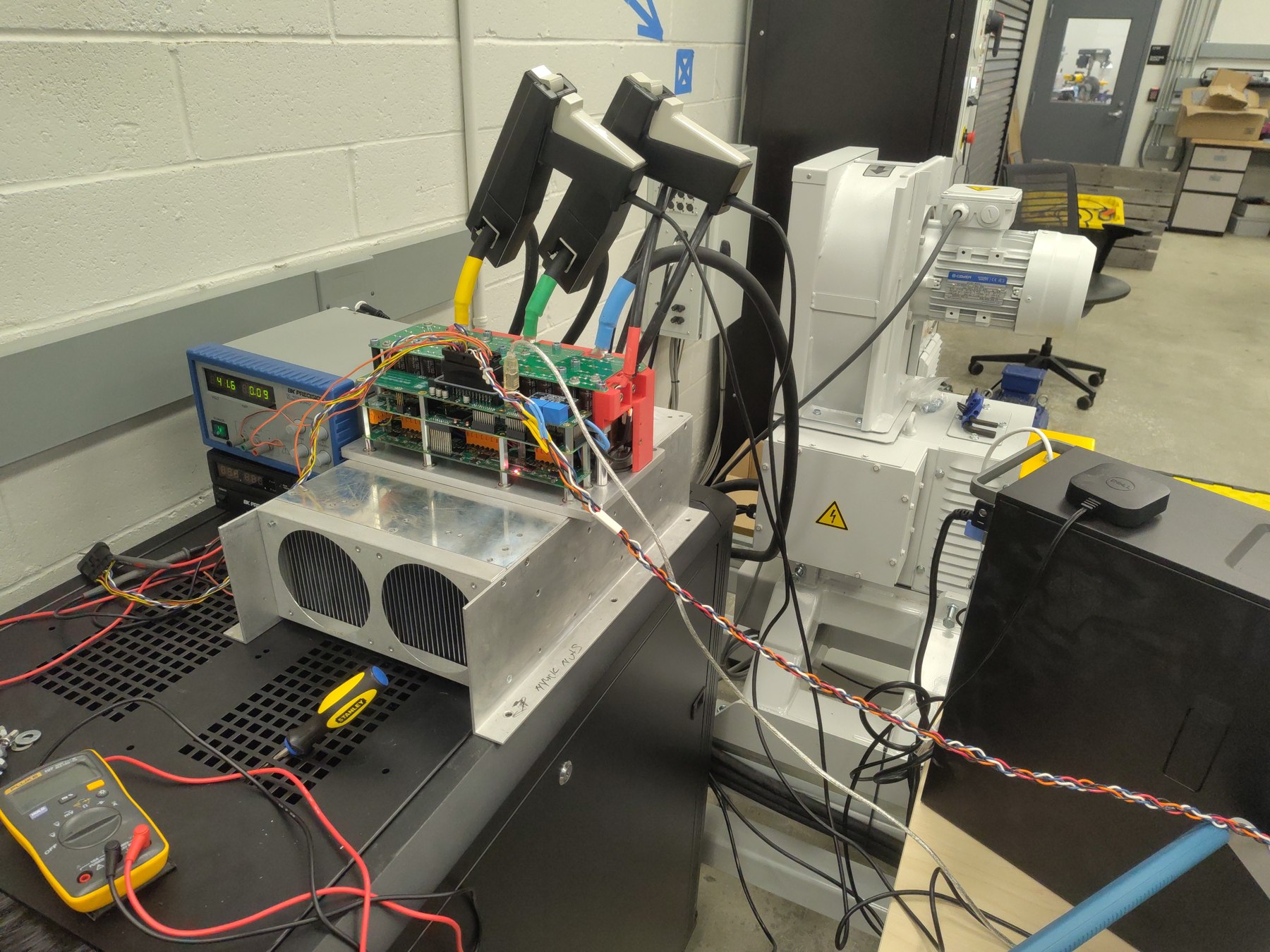
- DUT: OpenVVVF Gen7 size 2 inverter hardware.
- Cooling assembly: Heatsink installed without thermal interface material. Phase-lead interference tilted it backward and left a gap at the contact surface.
- Machine: Motor coupled to a Sierra CP Engineering dynamometer; telemetry during the 200 A hold indicates approximately −1,100 RPM.
- DC supply: Nominal 50 V setting. The measured bus rose under regeneration.
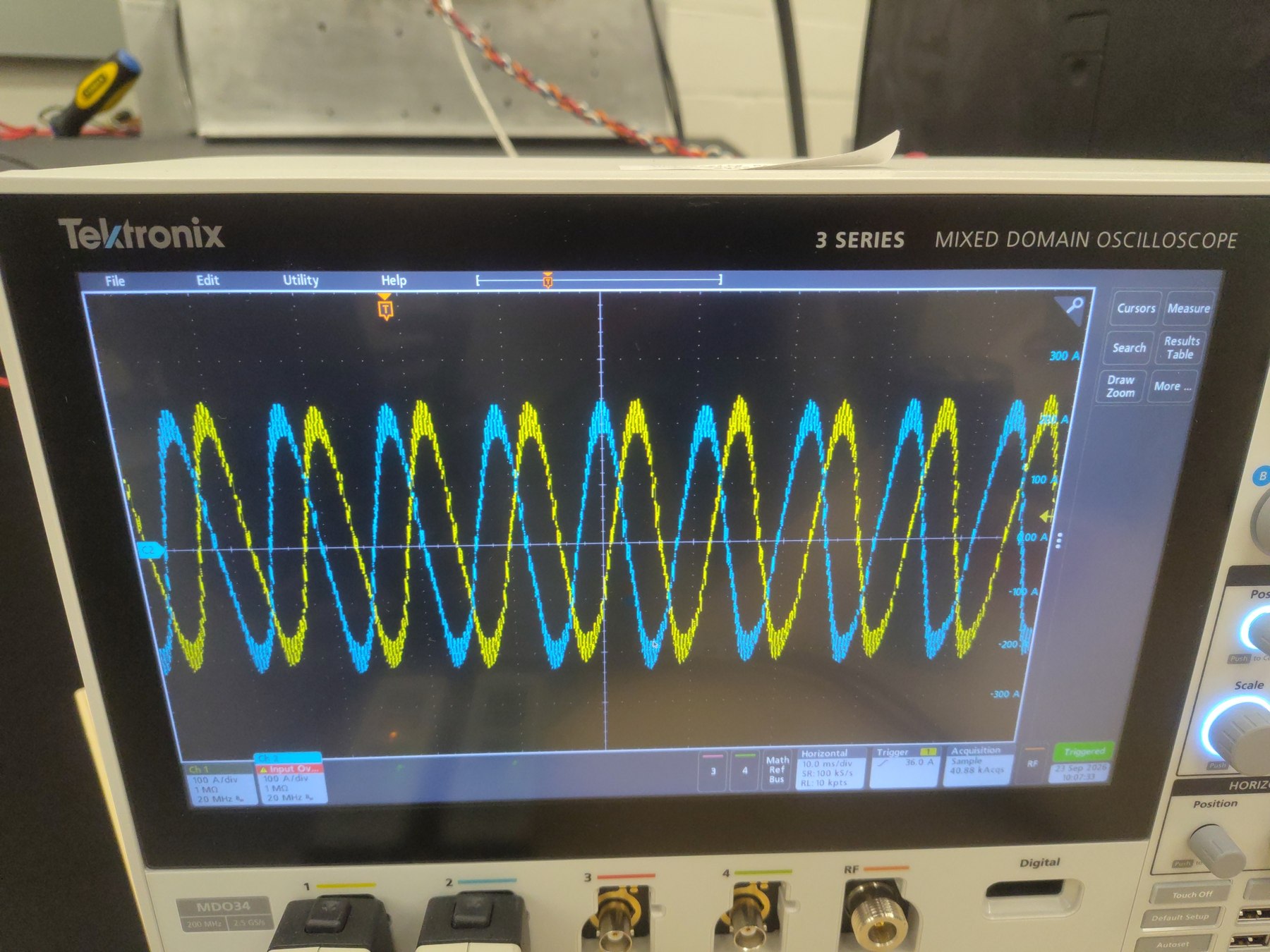
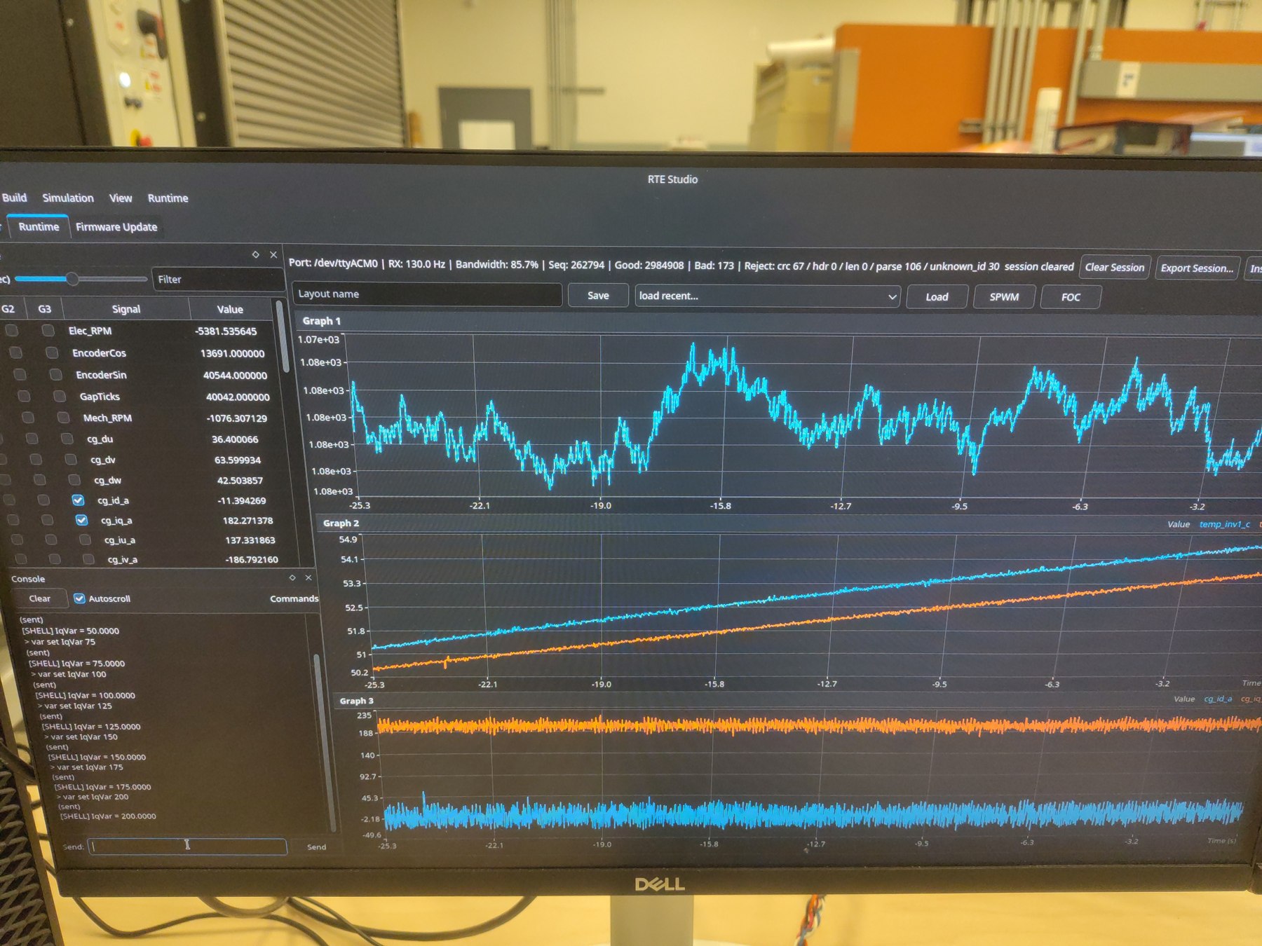
- Instrumentation: RTE Studio telemetry, Tektronix 5 Series MSO, and Klein Tools TI250 thermal imager.
Test conditions
| Parameter | Value |
|---|---|
| Hardware | Gen7 size 2 |
| Nominal bus setting | 50 V |
| Bus during 200 A hold | 58.1 V average; 51.5–58.9 V range through the 79 °C split |
| Current command | IqVar: 25, 50, 75, 100, 125, 150, 175, then 200 A |
| Time at 200 A to 79 °C split | 9 min 15 s |
| Average DC-link power at 200 A | 3.14 kW into the DC link |
| Regen energy through split | Approximately 0.485 kWh, integrated from logged DC-link power |
| Heatsink interface | No thermal interface material; visible gap caused by phase-lead interference |
Procedure
- Enabled the inverter and allowed the dynamometer to bring the coupled machine to operating speed.
- Increased
IqVarin the recorded 25 A steps through 200 A. - Held the 200 A command while logging telemetry and observing the baseplate NTCs.
- Split this report at the first
temp_inv2_c(TS2) sample at or above 79 °C, at t = 619.492 s. The remainder of the same source recording is analyzed in the OTP report.
Electrical results
Per-command statistics from the full-rate telemetry log through the 79 °C analysis boundary (Pdc = DC-link power, Idc = DC-link current):
| Iq command | Step duration | Avg Iq | Peak phase current | Avg Pdc | Avg Idc |
|---|---|---|---|---|---|
| 25 A | 3.8 s | 22.4 A | 33 A | 390 W | 8 A |
| 50 A | 1.9 s | 44.5 A | 53 A | 713 W | 14 A |
| 75 A | 1.5 s | 69.5 A | 83 A | 1.06 kW | 21 A |
| 100 A | 1.5 s | 93.9 A | 110 A | 1.42 kW | 28 A |
| 125 A | 1.2 s | 118.6 A | 135 A | 1.89 kW | 38 A |
| 150 A | 1.9 s | 146.0 A | 162 A | 2.37 kW | 48 A |
| 175 A | 1.6 s | 168.8 A | 187 A | 2.73 kW | 53 A |
| 200 A hold to split | 9 min 15 s | 200.0 A | 224 A | 3.14 kW | 54.0 A |
During the 200 A interval to the split, measured bus voltage averaged 58.1 V and peaked at 58.9 V. Instantaneous phase-current samples reached approximately +224 A and −208 A. The data show sustained regenerative power flow throughout the analyzed interval.
Thermal results
At the selected split point, temp_inv2_c (baseplate TS2) first crossed 79 °C. Temperatures rose from the initial NTC readings as follows:
- Baseplate TS1 (
temp_inv1_c): 34.5 °C → 76.7 °C at the split. - Baseplate TS2 (
temp_inv2_c): 37.6 °C → 79.0 °C at the split.
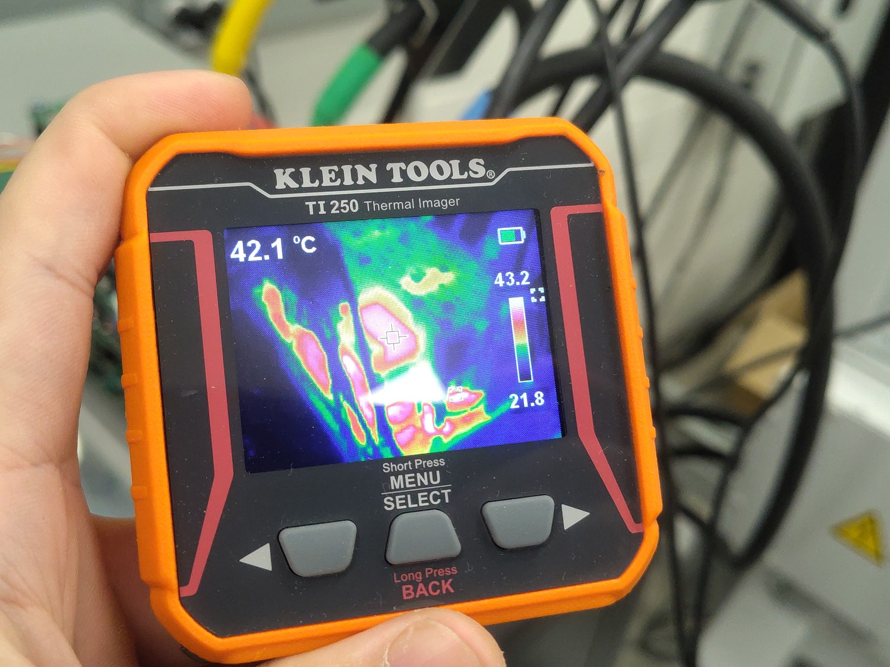
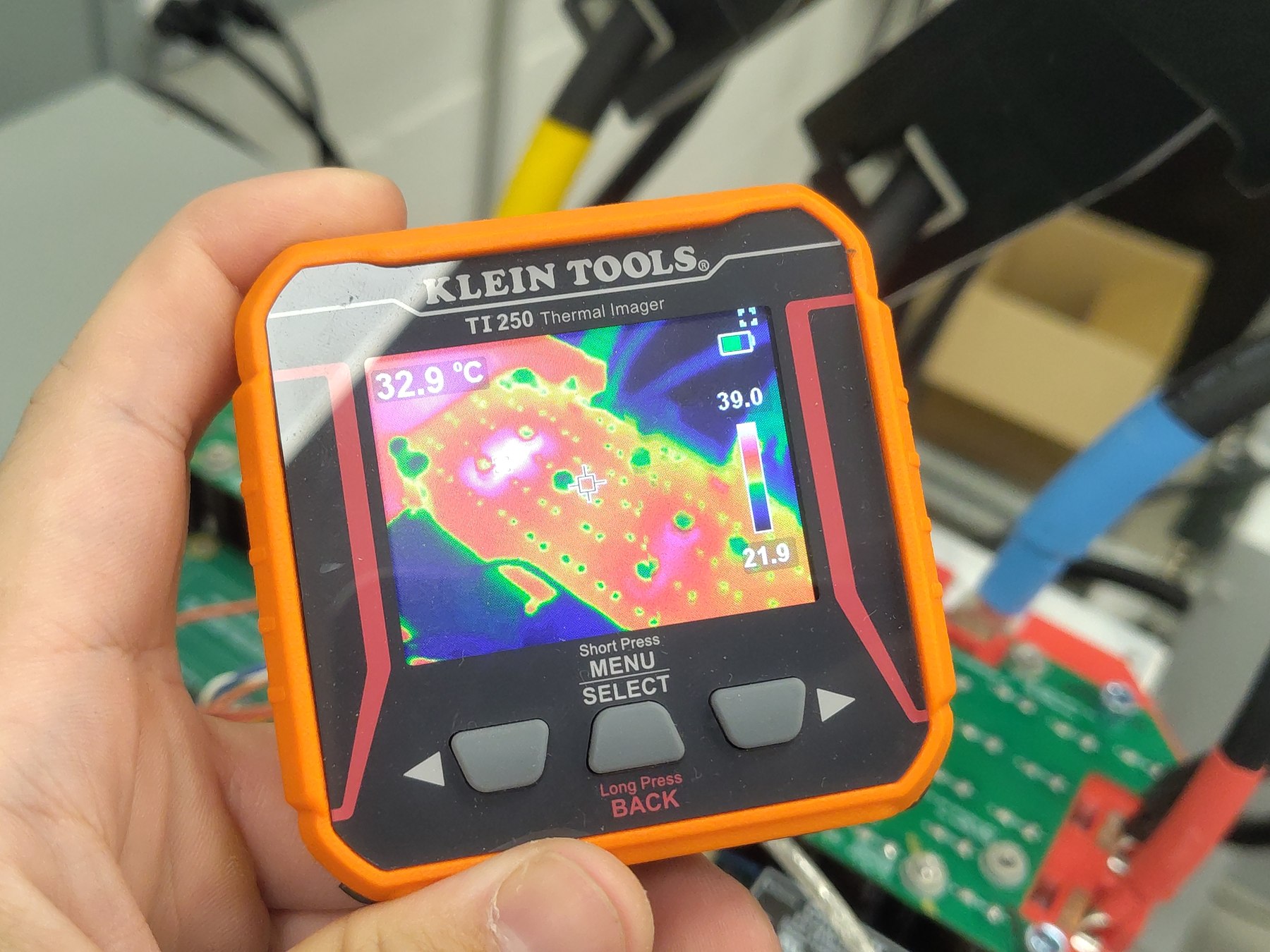
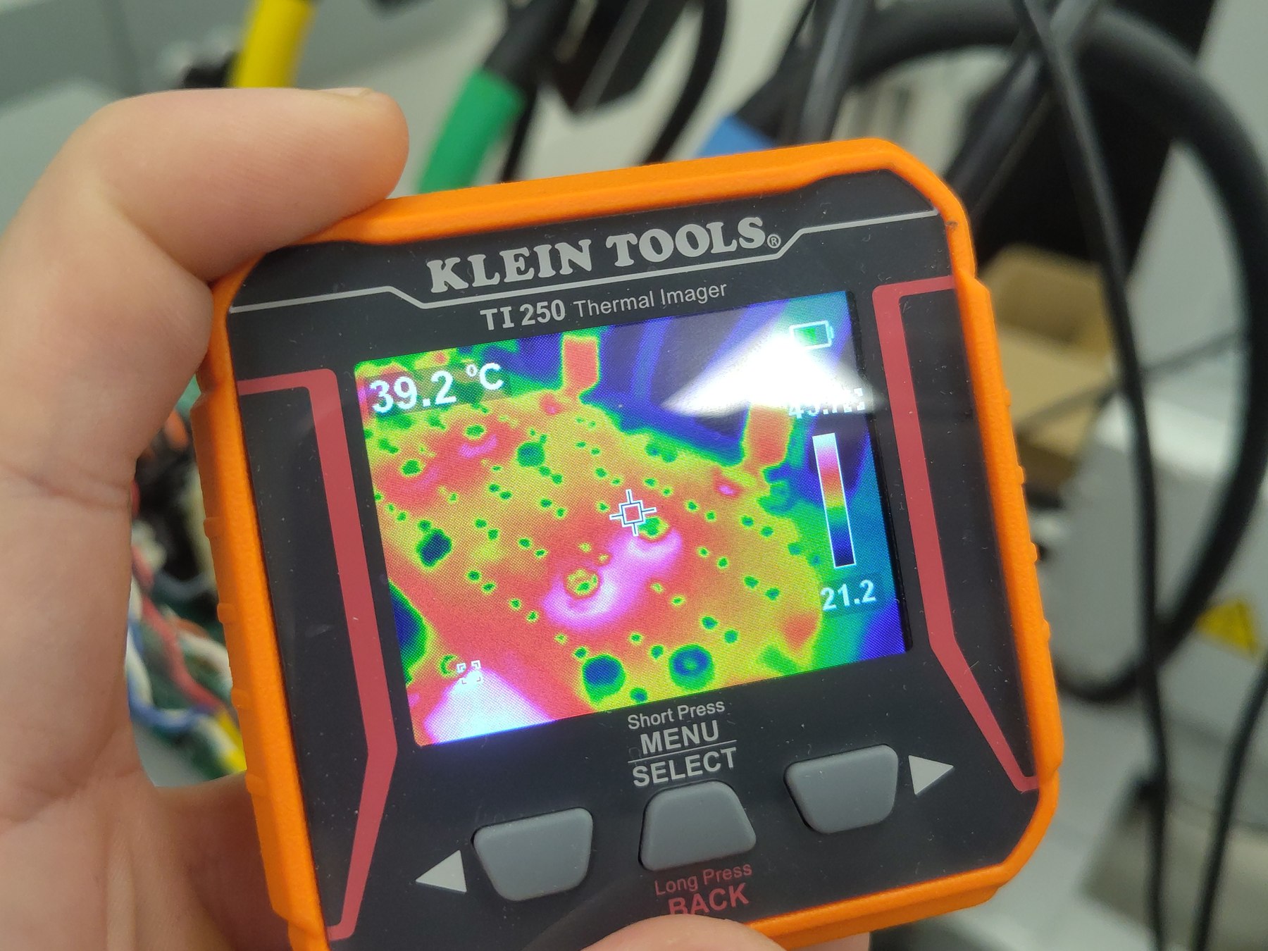
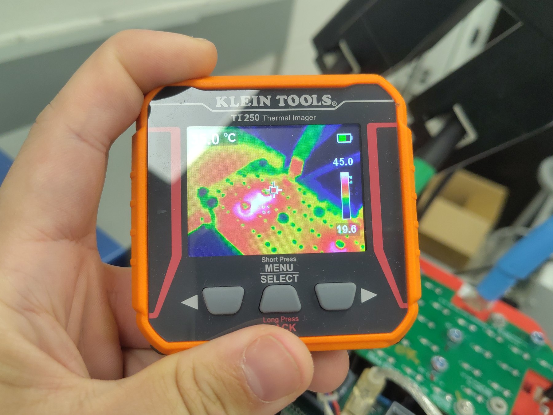
The TI250 photos show exterior spot readings of 42.1 °C, 32.9 °C, and 39.2 °C. These are individual crosshair measurements on auto-scaled thermal images and are not a full surface-temperature survey.
Telemetry overview
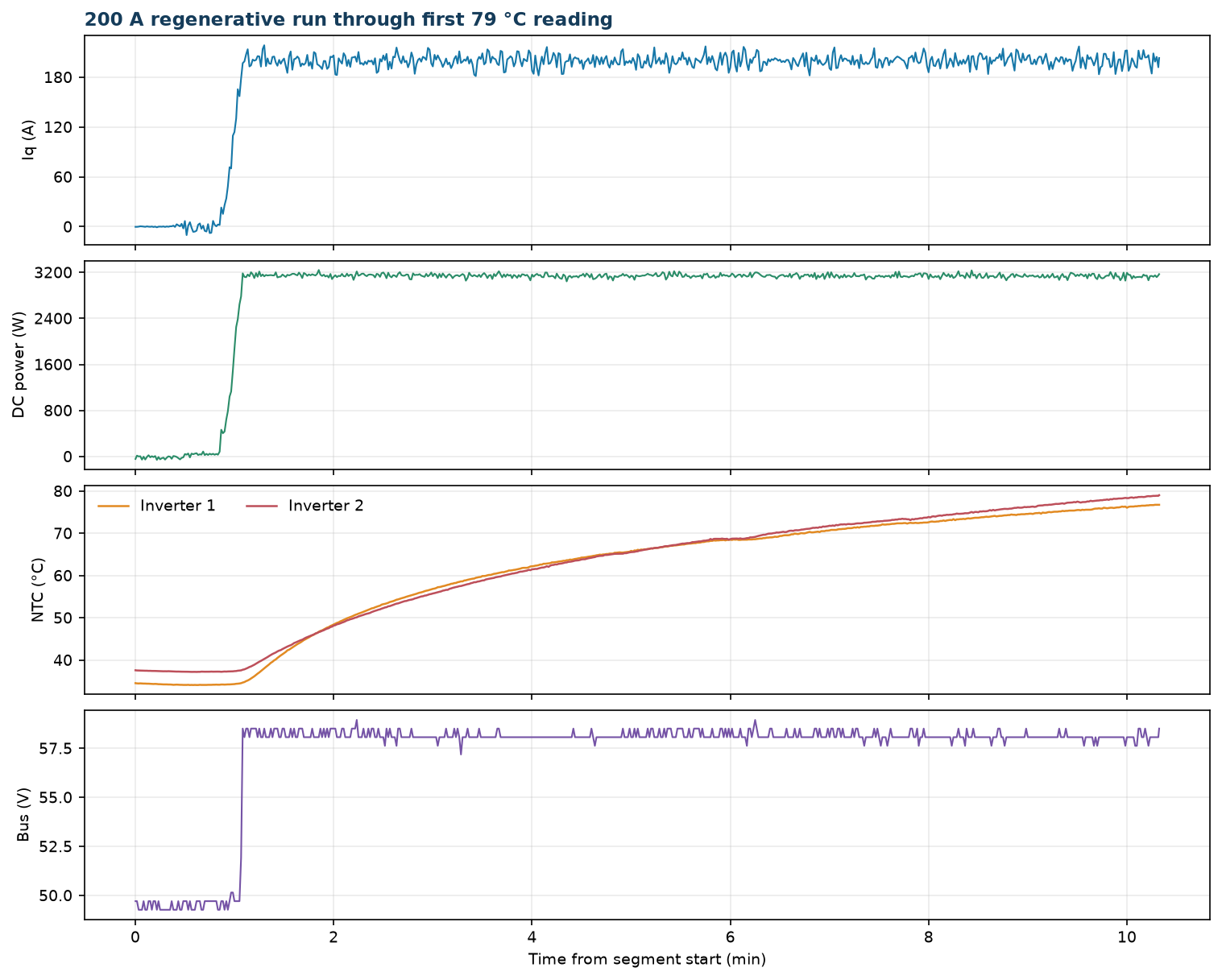
Open split telemetry: View the run through 79 °C in the Telemetry Viewer
Observations
- The inverter reached the 79 °C reporting boundary after 9 min 15 s at the 200 A command, with approximately 3.14 kW average returned to the DC link.
- No fault state is recorded before the split point.
- The telemetry is continuous across the split. It does not show
IqVarbeing set to zero at 79 °C; the current remains at the 200 A command until the OTP trip described in the companion report. - The logged bus averaged 58.1 V under regeneration, although the bench supply was set for nominal 50 V.
- Machine-terminal power is not quoted for this run: P = (3/2)(vd·id + vq·iq) from this session's logged dq voltages (firmware build
cd4d65f5c2181738) does not reconcile with DC-link power — it would imply ≈3 kW of inverter dissipation, which the observed temperature rise (44 K in 10 minutes on the dry-mounted heatsink) rules out. The dq-voltage calculation reconciles in the later build855dbcee90d611cband is reported from the 400 A run onward. - The heatsink gap and absent thermal interface material prevent this run from establishing the thermal performance of a correctly mounted heatsink.
temp_inv3_c(TS3) andtemp_motor_care unpopulated in this recording.
Conclusion
Pass for the 200 A regenerative heating segment through 79 °C. Gen7 size 2 hardware sustained the 200 A q-axis command while returning approximately 3.14 kW to the DC link, reaching the selected 79 °C sensor threshold without a fault before the report boundary. The source recording continues into a thermal OTP event; that response is documented separately. Temperature conclusions apply only to this assembly, where the heatsink had a gap and no thermal interface material.
Artifacts
- Split telemetry log (JSONL, approximately 1 sample/s) — open in Telemetry Viewer
- Telemetry overview plot
- Full source telemetry log, retained for traceability
- Photos: dynamometer setup, second setup view, scope, RTE Studio
- Thermal images: view 1, view 2, view 3, view 4
- Dynamometer setup video