18 · v0.2 · 2026-09-23Download PDF
| Doctype | Test Report |
|---|---|
| Product line | openvvvf |
| Applies to | openvvvf-control-module, chassis-size-2 |
| Version | 0.2 |
| Date | 2026-09-23 |
| Description | Motoring-direction counterpart to the 200 A steady-state regen test, same thermally-pasted Gen7 size 2 assembly and same evening. The inverter applied 200 A of positive torque current to the dynamometer-coupled PMSM for 42 minutes, drawing 2.46 kW from the ~145 V DC link. Baseplate NTCs plateaued at 43.6 / 43.5 °C — about 0.9 K below the regen run's plateau, tracking the cooler night ambient rather than any directional difference. |
| Test id | 18 |
| Nav order | 367 |
| Normative refs | OV-TEST-HW-INDEX, OV-TEST-HW-REGEN-200A-STEADY-STATE-GEN7-SIZE2 |
200 A Motoring Steady-State Thermal Test — Gen7 Size 2
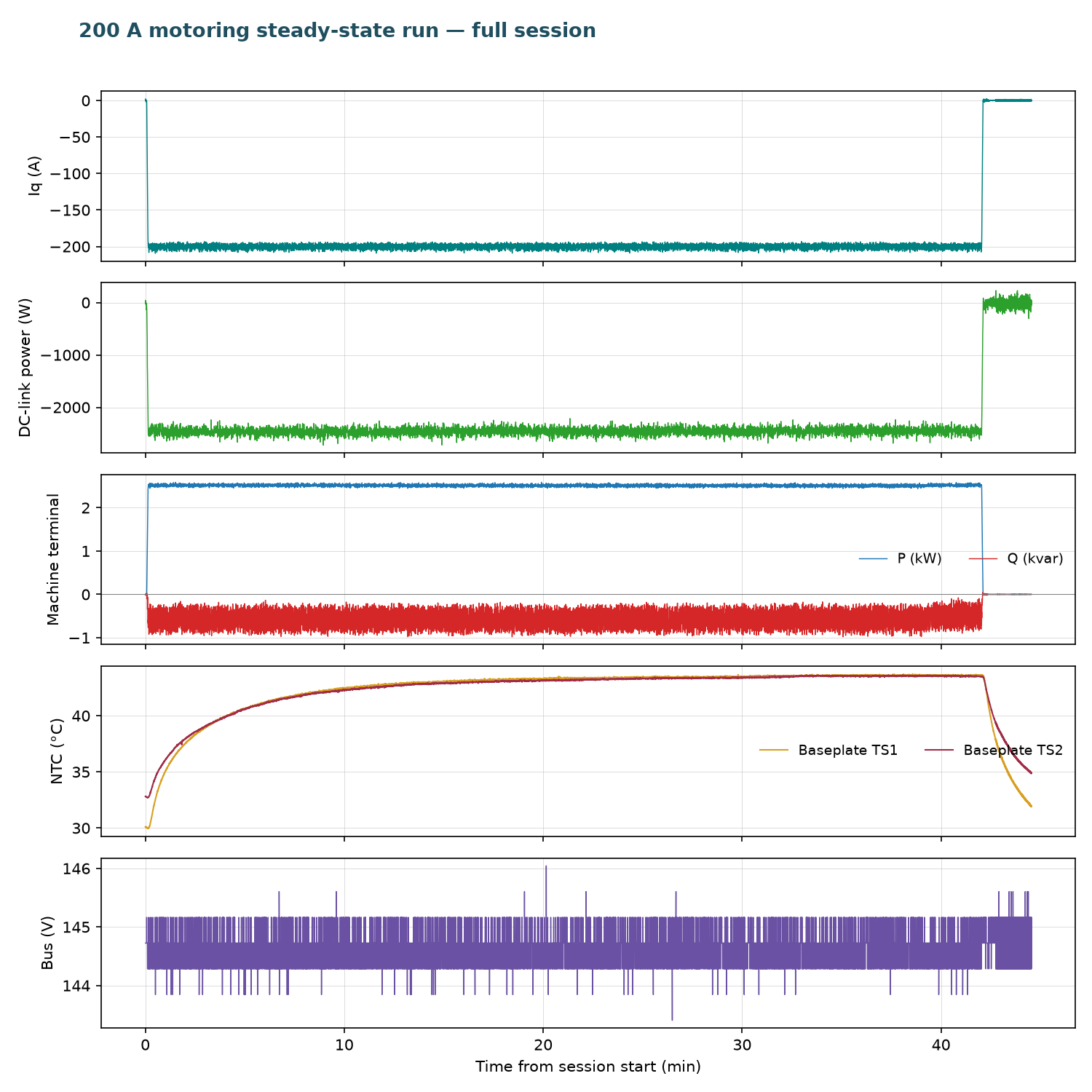
This report is the motoring-direction counterpart to OV-TEST-HW-REGEN-200A-STEADY-STATE-GEN7-SIZE2, run the same evening on the same thermally-pasted assembly: instead of absorbing regen power, the inverter applied 200 A of positive-torque current to the dynamometer-coupled PMSM for 42 minutes, drawing 2.46 kW average from the ~145 V DC link while the dynamometer held the shaft near −470 RPM.
The steady-state plateau came in at 43.6 °C (TS1) / 43.5 °C (TS2) — about 0.9 K below the regen run's 44.4 / 44.0 °C. Ambient was not logged, but the operator noted the night-cooled building ran roughly that much cooler, and the TI250's coldest pixels dropped from ~22.6 °C-class readings accordingly. Accounted for ambient, both directions land on the same temperature rise: at 200 A, inverter dissipation is conduction-dominated and does not care which way power flows.
Test setup
- DUT: OpenVVVF Gen7 size 2 (C2) power stage, thermally-pasted interface (same assembly as the regen steady-state run); firmware
foc_demograph (hash855dbcee90d611cb, same build as the preceding run — OpenVVVF/RTE commit5b529e2). - Machine: PMSM/IPM (10 poles) coupled to the Sierra CP Engineering dynamometer at approximately −470 RPM mechanical during the hold.
- DC supply: Sorensen bench supply at ~145 V, sourcing ~17 A — no load bank in the loop.
- Instrumentation: RTE Studio telemetry, Tektronix 5 Series MSO, Klein Tools TI250 thermal imager.
Test conditions
| Parameter | Value |
|---|---|
| Hardware | Gen7 size 2 (C2), pasted interface; firmware foc_demo hash 855dbcee90d611cb (RTE commit 5b529e2) |
| Machine | PMSM/IPM, 10 poles, ~−470 RPM mech during hold |
| Bus | ~144.6 V average (143.4–146.0 V) |
| Current command | IqVar = −200 (motoring / positive torque), 42.0 min |
| Average Iq over hold | −199.9 A |
| DC-link power | −2.46 kW average (supply sourcing; −2.72 kW max draw) |
| Energy drawn from DC link | ≈1.72 kWh |
| Machine terminal real power P | +2.51 kW mean (motoring; delivered to the machine — calculated from logged cg_vd_v/cg_vq_v/cg_id_a/cg_iq_a) |
| Machine reactive power Q | ≈0.57 kvar mean (machine magnetizing demand; quoted as magnitude — sign follows the logged dq frame) |
| Machine apparent power |S| | 2.58 kVA mean |
| Power factor (calculated) | 0.972 |
| Inverter efficiency (calculated) | ≈100% at the 2.5 kW scale (telemetry offsets dominate at this level) |
| Ambient | not logged; ~0.9 K cooler than the regen run per operator (night-cooled building) |
| Baseplate NTC at steady state | TS1 43.6 °C, TS2 43.5 °C |
Procedure
- Powered up and started control — clean boot this session, in contrast to the regen run's startup gate-driver transients;
RUNNINGfrom t ≈ 0.1 s with no faults at any point. - Commanded
IqVar = −200at t = 4.2 s (slew-limited ramp to full current) and held it for 42.0 minutes. - Took oscilloscope, telemetry-screen, and TI250 thermal photos once the baseplate had plateaued, then commanded
IqVar = 0at t = 2522.5 s and logged the cooldown.
Electrical results
- Current: −199.9 A average Iq, tight regulation throughout.
- DC link: −17.0 A average / −2.46 kW average drawn from the bus — the supply sources motoring power where the regen run's link returned it. (Sign convention as logged: negative DC-link power = power leaving the link.)
- Bus: 144.6 V average, rock steady with no clamp hardware involved.
- Protection:
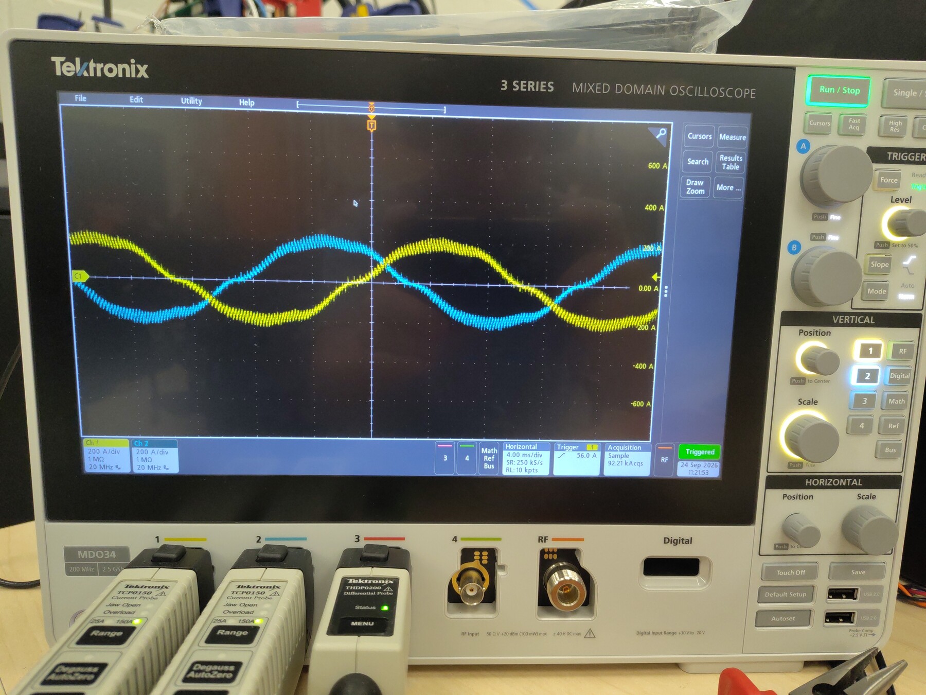
gate_fault= 0 for the entire session,cg_vlimit_scale= 1.000 throughout, no overcurrent events. - The motoring current waveforms on the oscilloscope are clean sine waves — a useful contrast against the 400 A run's clamp-saturation artifacts, with appropriately rated measurement in the loop this time.
- Machine-terminal power (calculated): from the logged dq quantities (peak-amplitude convention, P = (3/2)(vd·id + vq·iq), Q = (3/2)(vq·id − vd·iq)), the machine absorbed 2.51 kW mean while drawing ≈0.57 kvar of magnetizing reactive power (quoted as magnitude) — 2.58 kVA, power factor ≈ 0.972. Machine-terminal power and the 2.46 kW DC-link draw agree within ~2% — calculated inverter efficiency ≈ 100% at this power, where telemetry offsets dominate the difference.
Thermal results
- Baseplate TS1 (
temp_inv1_c): 30.0 °C at the start of the hold → plateau 43.6 °C (last-10-minute average 43.58 °C). Equilibrium by ~25 minutes. - Baseplate TS2 (
temp_inv2_c): 32.8 °C → plateau 43.5 °C. - Versus the regen run: the regen-direction plateau was 44.4 / 44.0 °C in an ambient the operator logged at 22.5 °C; this run plateaued 0.8–0.9 K lower in an ambient roughly 0.9 K cooler. The rise over ambient is the same within measurement uncertainty — direction-independent thermal behavior at 200 A, as expected for conduction-dominated losses.
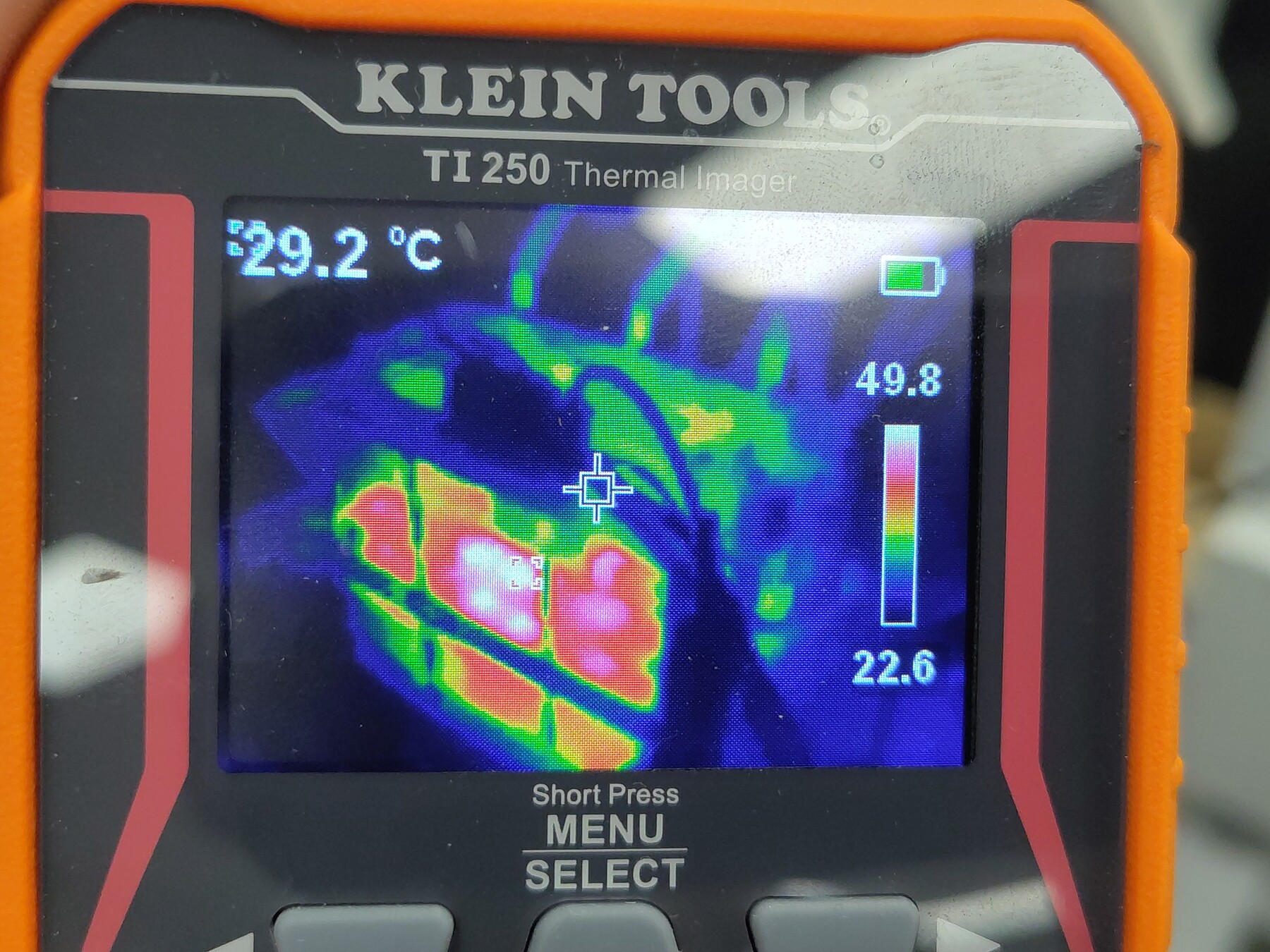
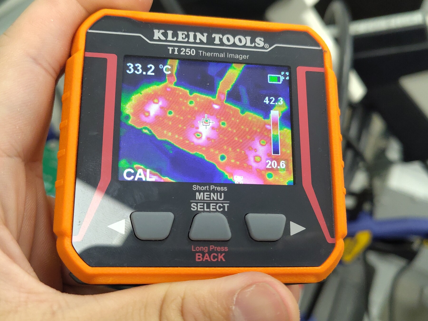
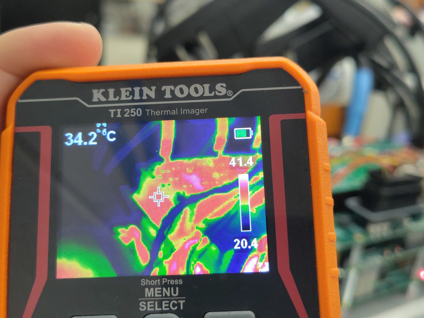
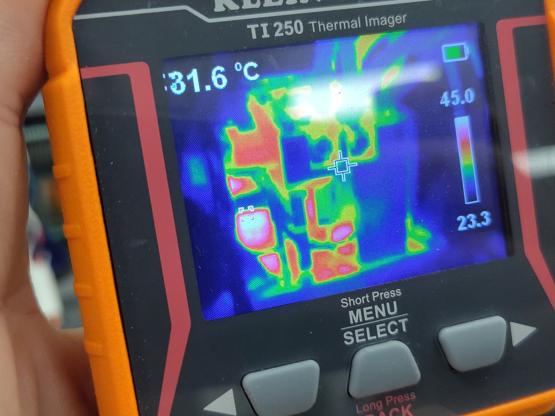
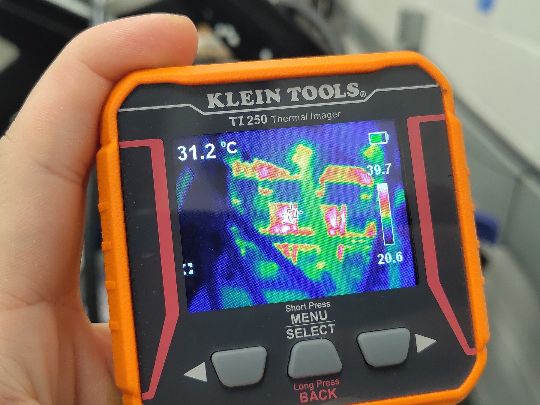
- TI250 spot readings during the photo pass: crosshair 29.2–34.2 °C across views, with coldest pixels at 20.4–24.6 °C depending on framing — consistent with the cooler night room:
Telemetry overview
Open full session: View the run in the Telemetry Viewer
Observations
- Boot was clean — no gate-driver or phase-overcurrent transients, unlike the regen steady-state session earlier that evening. Both sessions share the same firmware build; the difference appears to be power-up state rather than software.
- The DC link here sources ~2.5× the power the regen run returned (~2.46 kW drawn vs 0.95 kW returned) at the same 200 A and similar shaft speed — motoring supplies both machine copper loss and shaft power, while regen only returns the shaft-derived EMV component.
- Shaft speed held near −470 RPM throughout, with a brief dip/spin transient around the stop at t = 2522 s.
- TS3 (
temp_inv3_c) remained disabled (wiring defect, unrelated to the test);temp_motor_cis unpopulated.
Conclusion
Pass. The thermally-pasted Gen7 size 2 assembly holds a continuous 200 A motoring command (2.46 kW drawn, ~145 V bus) at true steady state with baseplate temperatures of 43.6 / 43.5 °C — matching the regen-direction plateau once the cooler night ambient is accounted for. Bidirectional 200 A continuous-duty operation is validated on the pasted assembly.
Artifacts
- Decimated telemetry log (JSONL, 1 sample/s) — open in Telemetry Viewer
- Telemetry overview plot
- Full source telemetry log, retained for traceability
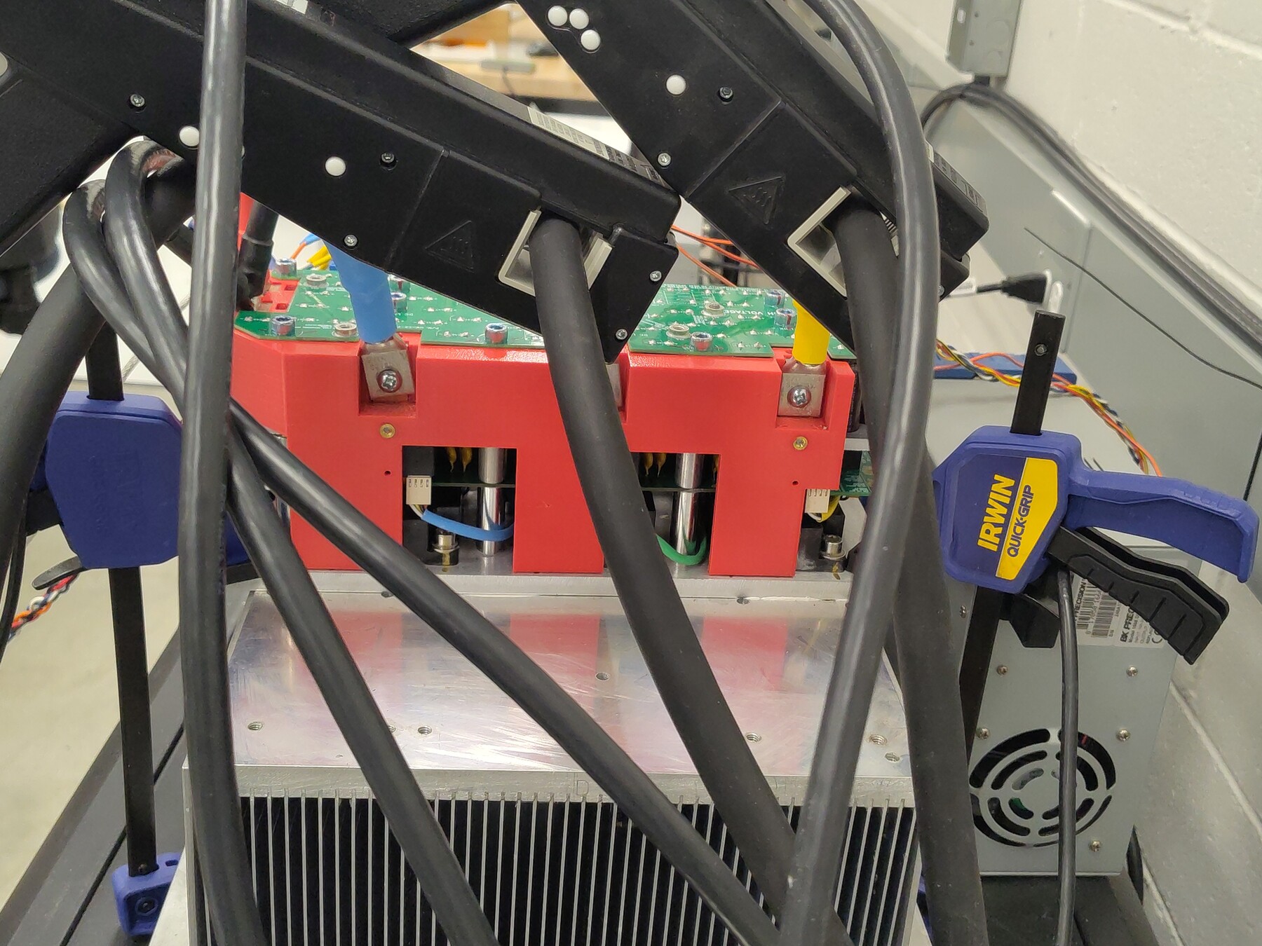
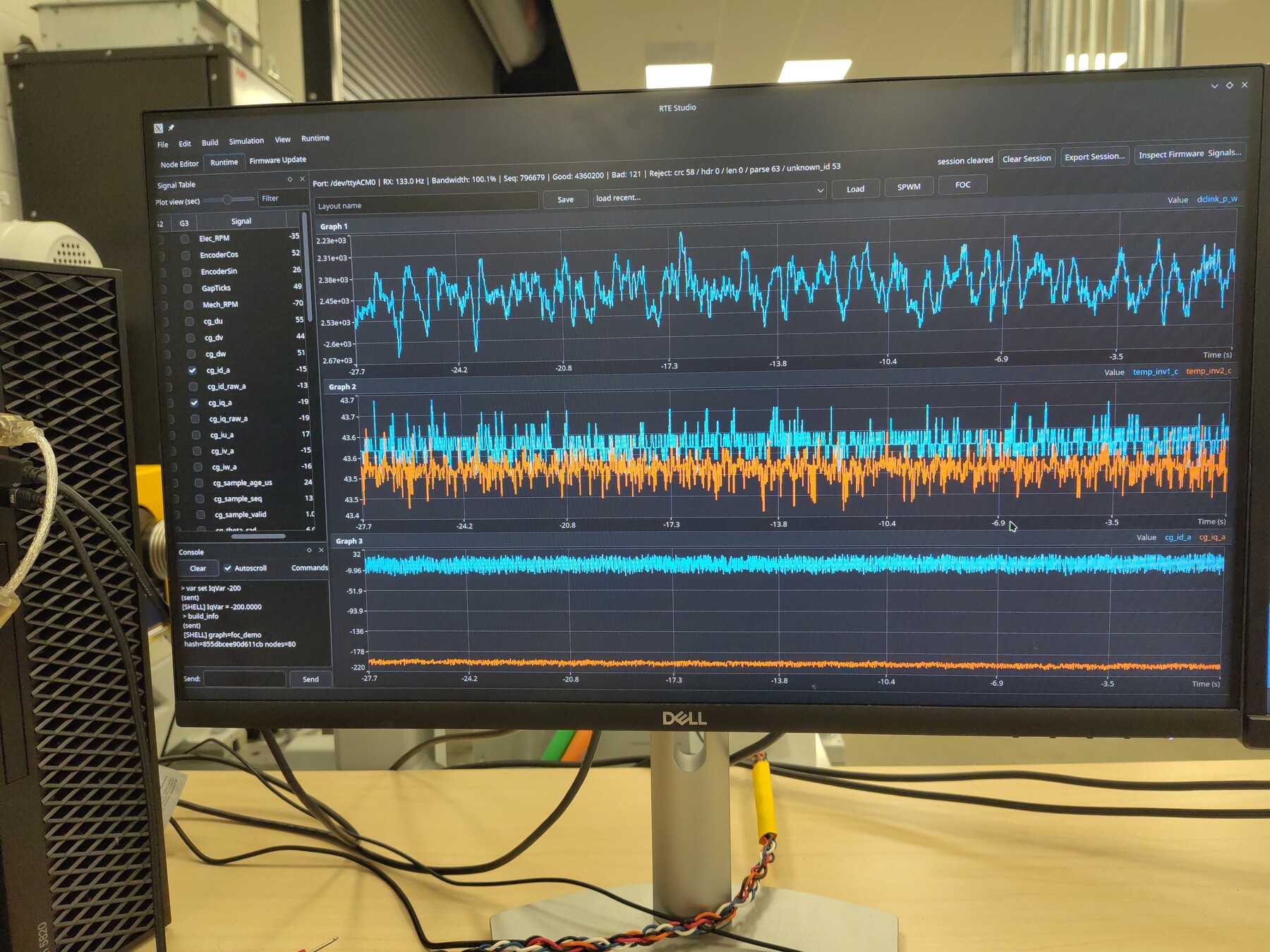
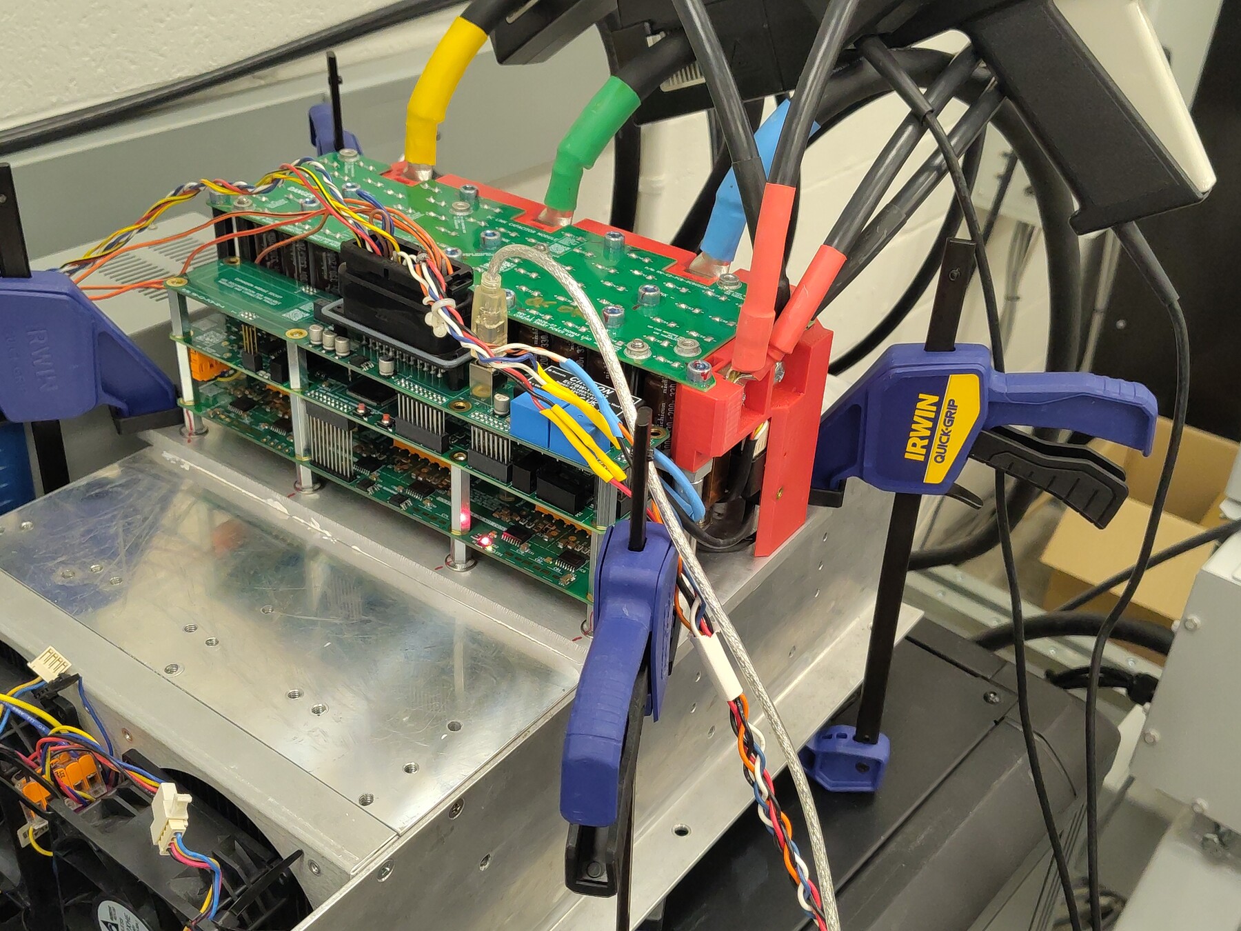
- Photos: motoring currents on scope, RTE telemetry screen, bench setup, power stage detail
- Thermal images: view 1, view 2, view 3, view 4, view 5
- Full-resolution originals of the photos are retained alongside as
*-Original.jpg.