
OV-C2-AG-10-GDWH · v0.8 · 2026-09-13Download PDF
| Doctype | Assembly Guide |
|---|---|
| Doc id | OV-C2-AG-10-GDWH |
| Product line | openvvvf |
| Applies to | chassis-size-2 |
| Version | 0.8 |
| Date | 2026-09-13 |
| Description | Build the wiring harness connecting the control assembly to the gate driver board, carrying gate-drive and voltage-sense signals. |
| Nav order | 233 |
| Placeholder | True |
| Normative refs | OV-C2-AG-INDEX |
Gate Drive and Voltage Sense Wiring Harness
This chapter covers building the wiring harness that connects the control assembly to the gate driver board, carrying the gate-drive and voltage-sense signals. The harness is built in stages: the gate-emitter twisted pairs for each IGBT first, then the phase-voltage and DC-link sense leads. This chapter is still being written: the desaturation leads and final splices are documented as the build progresses.
Safety
- Do not power the inverter until all crimps, housings, and routing are verified.
- Keep the work area clean; stray wire strands or metal debris can short high-voltage bus bars.
- Review the hazard analysis (OV-SAF-HARA-CORE) before starting.
Required materials and tools
| Item | Qty | Notes |
|---|---|---|
| 18 AWG twisted-pair wire, black/white | 1 length per pair | One pair per IGBT gate-emitter connection; six pairs total for the inverter |
FDFNYD1-110(5) nylon fully-insulated female quick-disconnect terminal, 2.8 mm (0.110 in) tab (HW-C2-HW-FDFNYD1-110-5-A) |
2 | Per pair; 12 per chassis per the BOM (6 pairs x 2 terminals) |
| Heat-shrink tubing, red and black | 1 piece per pair | Side identification: red = high-side switch, black = low-side switch |
| Heat-shrink tubing, yellow, green, and blue | 1 piece per pair | Phase identification: yellow = U, green = V, blue = W |
| TE Connectivity crimp terminals | 2 | Per pair; for the gate-driver-board end of the pairs |
| TE Connectivity connector housings, orange | 3 | One per phase; each carries that phase's high-side and low-side pairs |
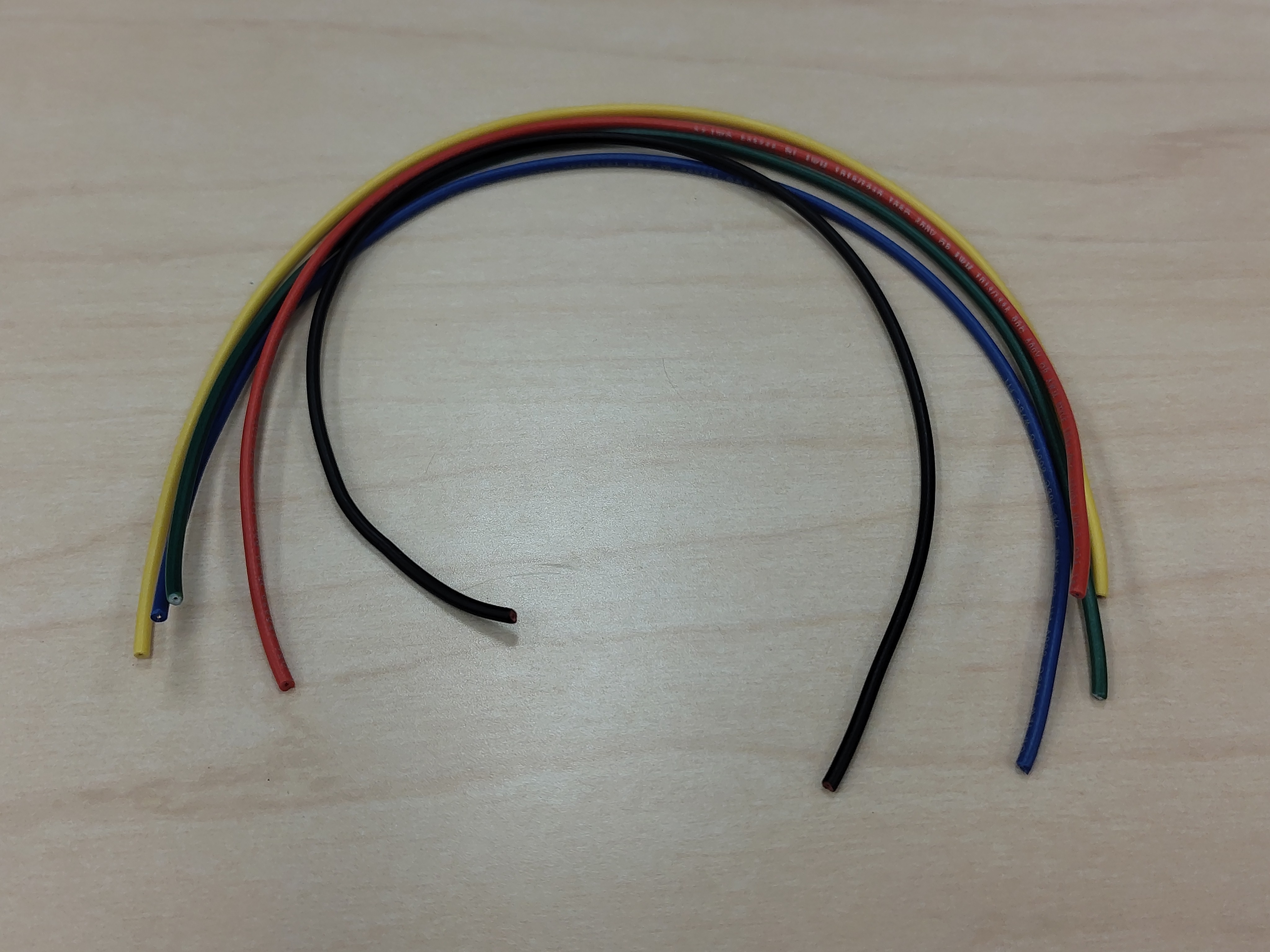
| Single-conductor wire, yellow, green, blue, red, and black | 1 each | Phase-voltage and DC-link sense leads |
| TE Connectivity connector housing, orange, 6-position | 1 | Voltage-sense housing; positions per the gate driver board silkscreen |
| Wire stripper | 1 | Sized for 18 AWG |
| Crimping tool | 1 | Sized for the quick-disconnect terminals used |
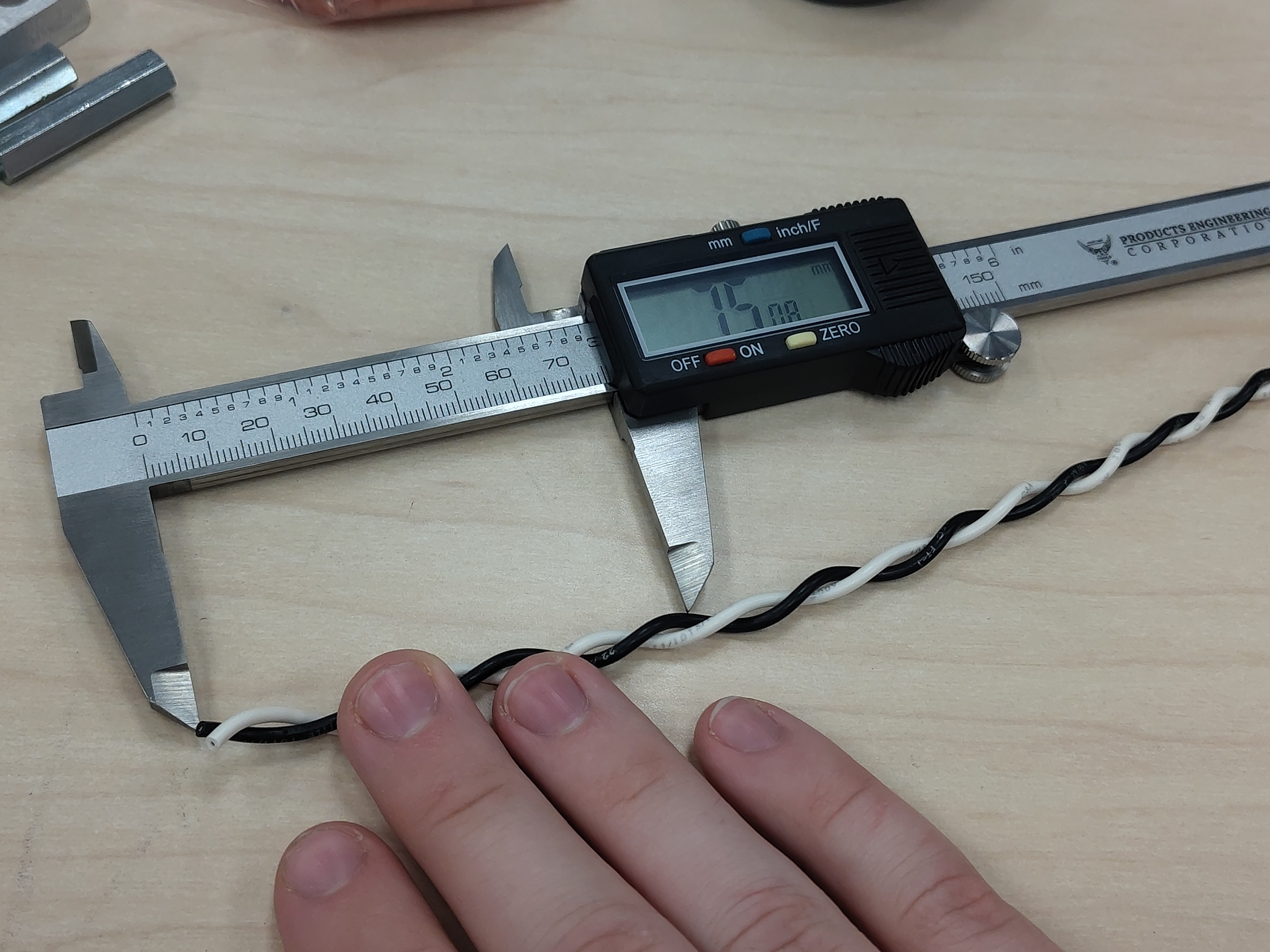
| Calipers | 1 | Helpful for consistent strip lengths |
| Flush cutters | 1 | For trimming wire and heat-shrink |
Step 1 - Cut a length of twisted pair
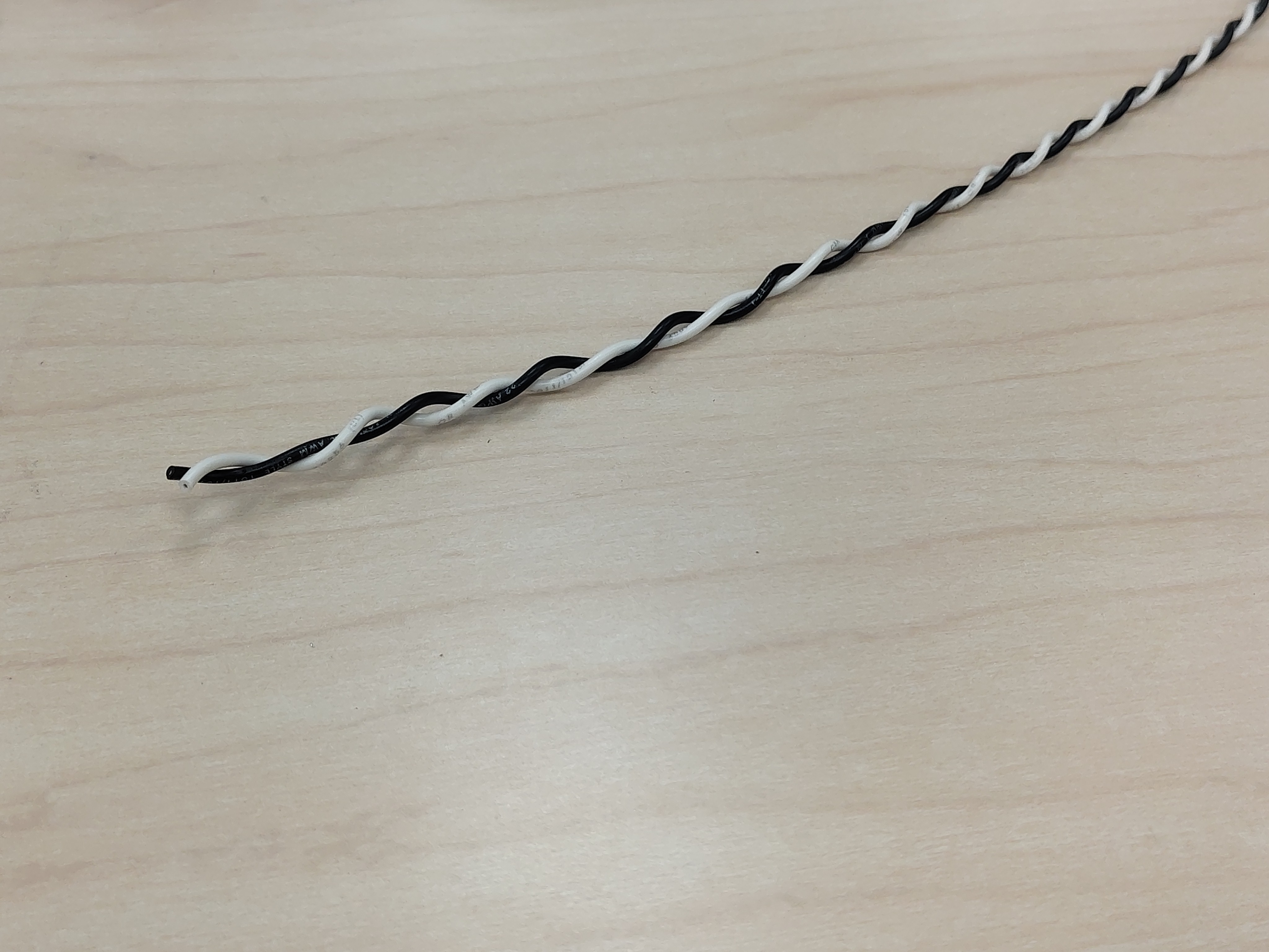
Each gate-emitter connection is a single twisted pair of 18 AWG wire (black and white). The twist keeps the loop area of the gate-drive circuit small, which matters at switching speeds — do not untwist the pair more than necessary at the ends.
There are six IGBT switches in the inverter (two per half-bridge module), so six pairs are needed in total. Cut each pair to a total length of 75 mm; keep the cut ends square.
Step 2 - Strip the wire ends
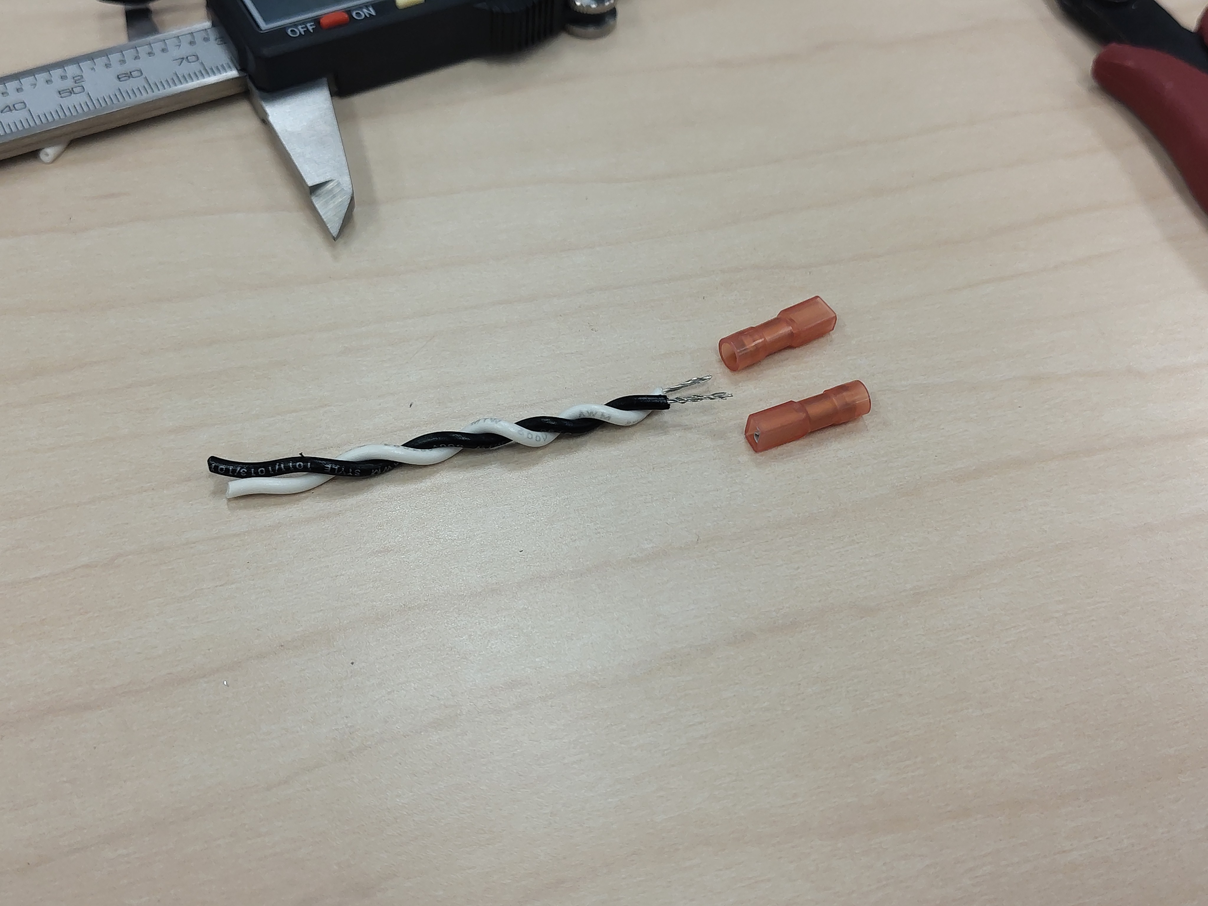
Strip the insulation from both conductors at each end of the pair, leaving enough bare wire to fill the terminal barrel. Keep the strip length consistent across all pairs.
Step 3 - Crimp the quick-disconnect terminals
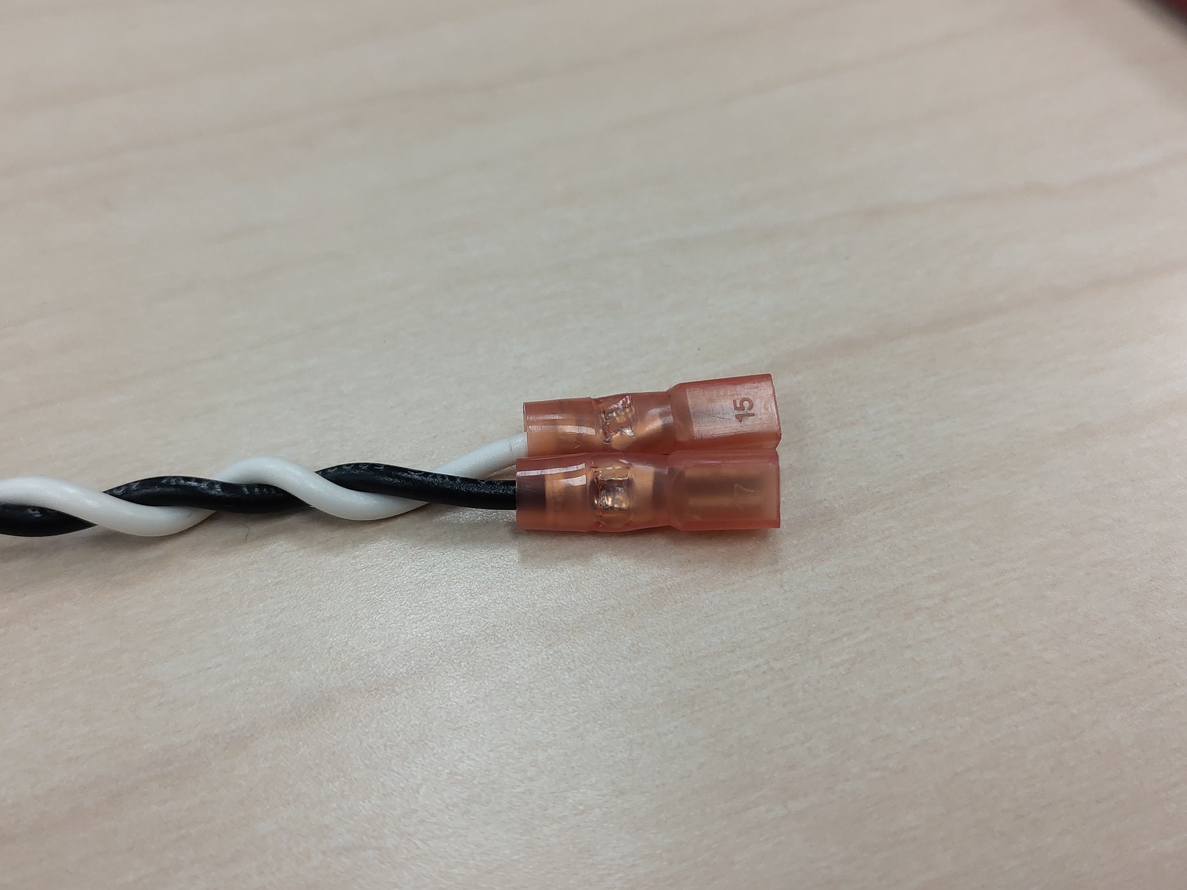
Crimp one insulated female quick-disconnect terminal onto each conductor. Keep the pair consistent: use the same conductor-to-terminal orientation on every pair so the later color-coded heat-shrink identifies the same signal everywhere.
Do not:
- Tin the wire with solder before or after crimping. Solder prevents the gas-tight cold weld and creates a brittle stress point.
- Nick or cut strands when stripping. If the strand count is reduced, cut back and re-strip.
Step 4 - Color-code the pair with heat-shrink
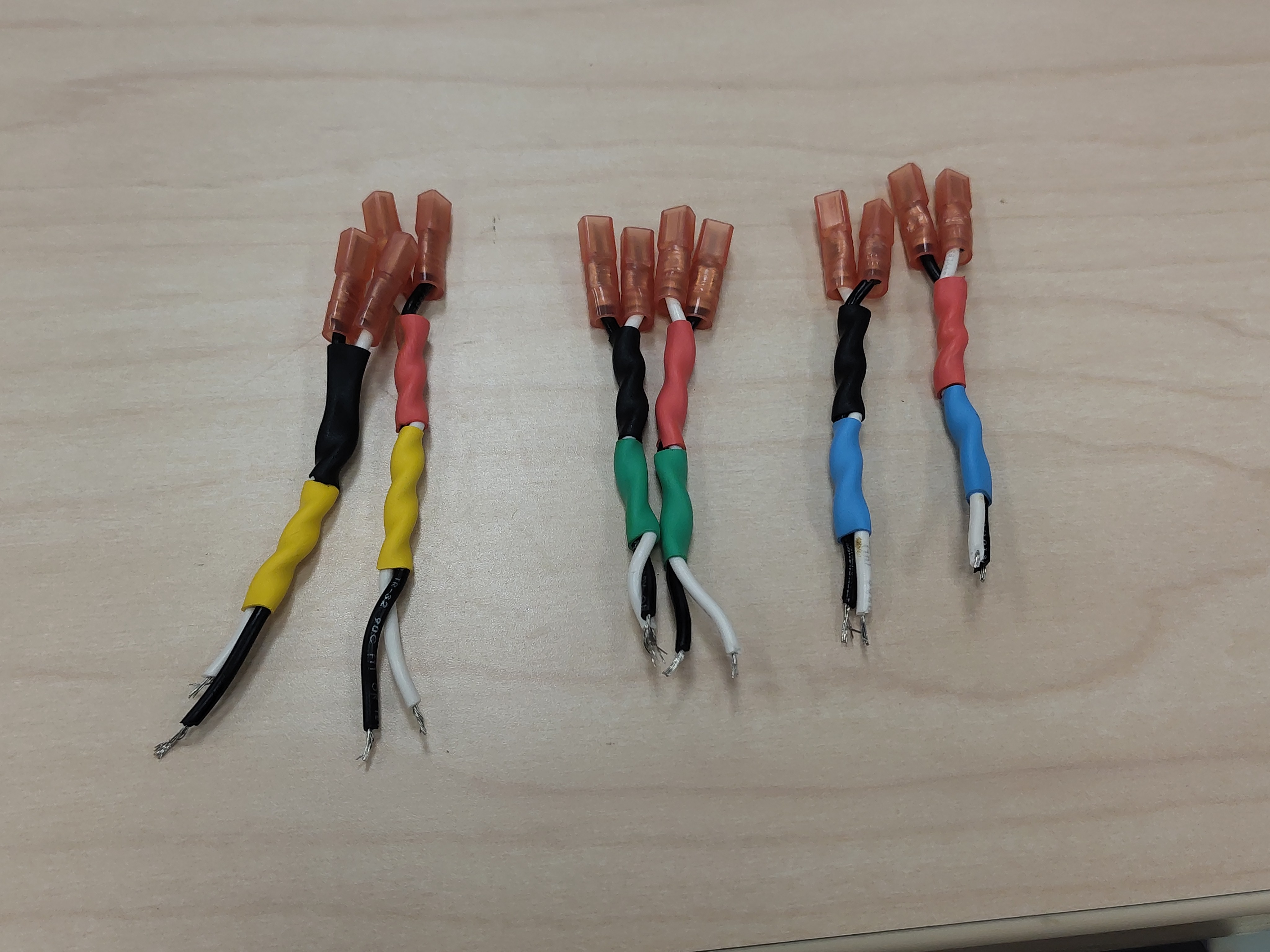
Each pair gets two pieces of heat-shrink: one for the switch side and one for the phase. The color code is:
| Heat-shrink color | Meaning |
|---|---|
| Red | High-side switch |
| Black | Low-side switch |
| Yellow | Phase U |
| Green | Phase V |
| Blue | Phase W |
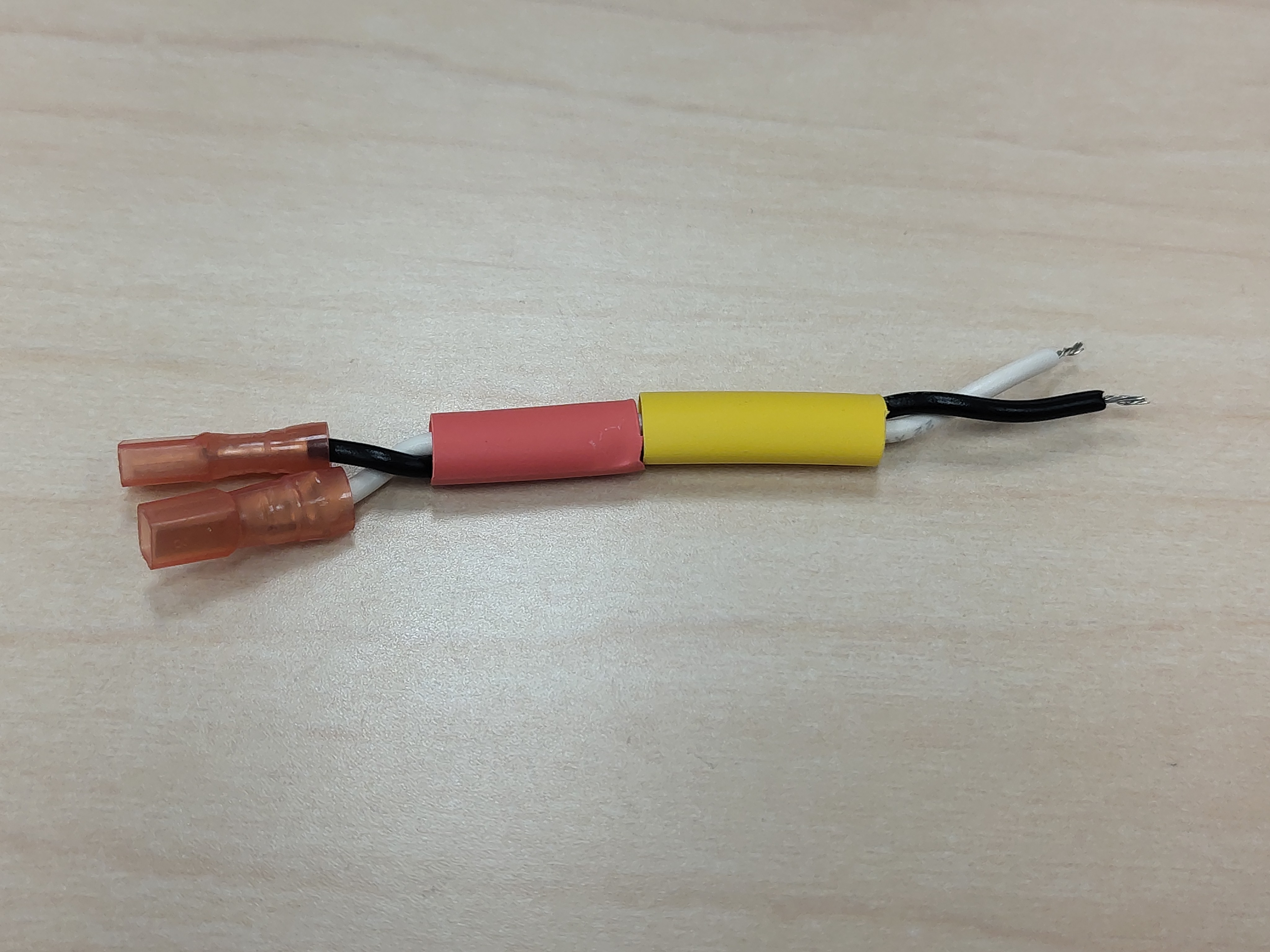
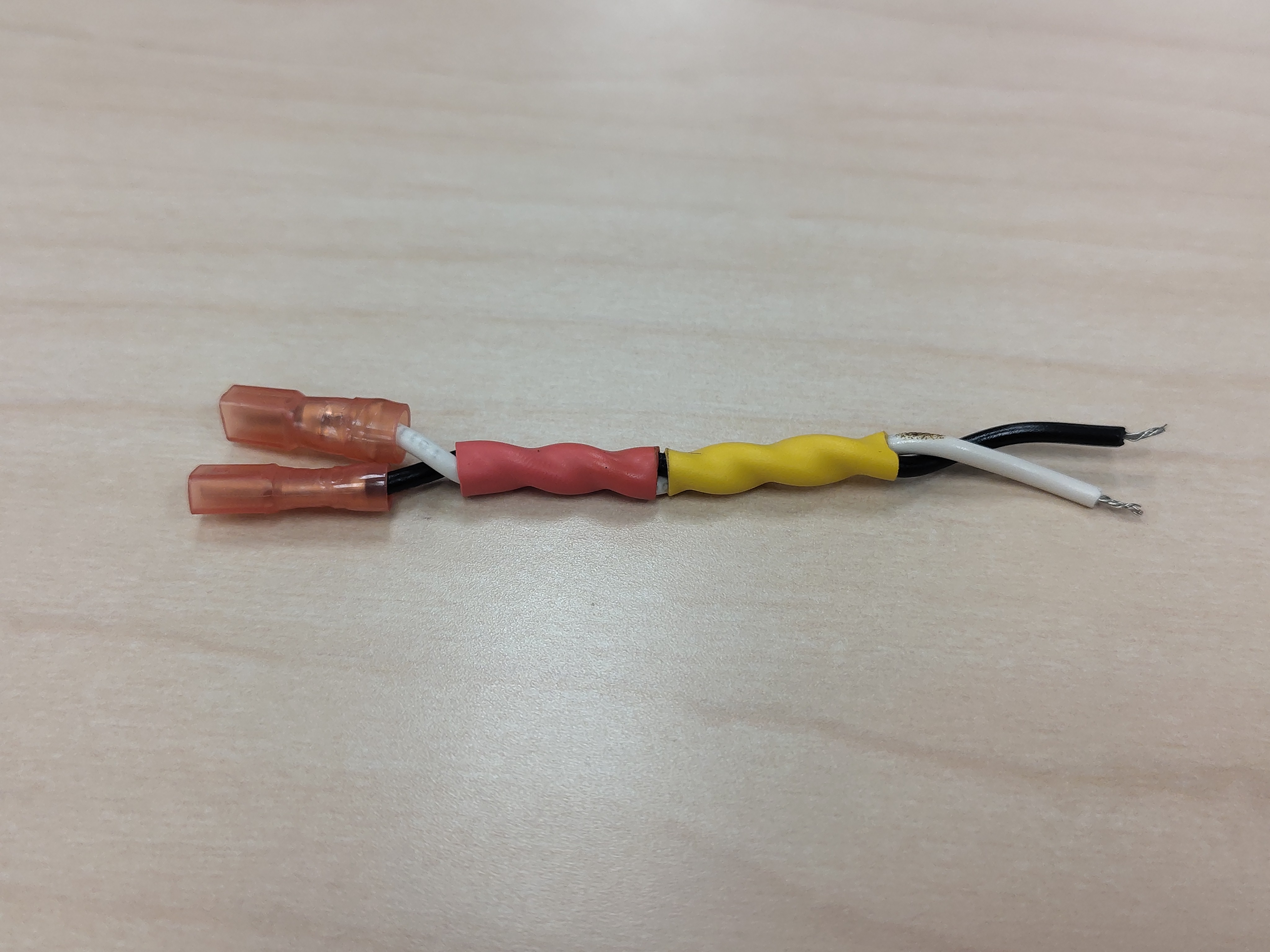
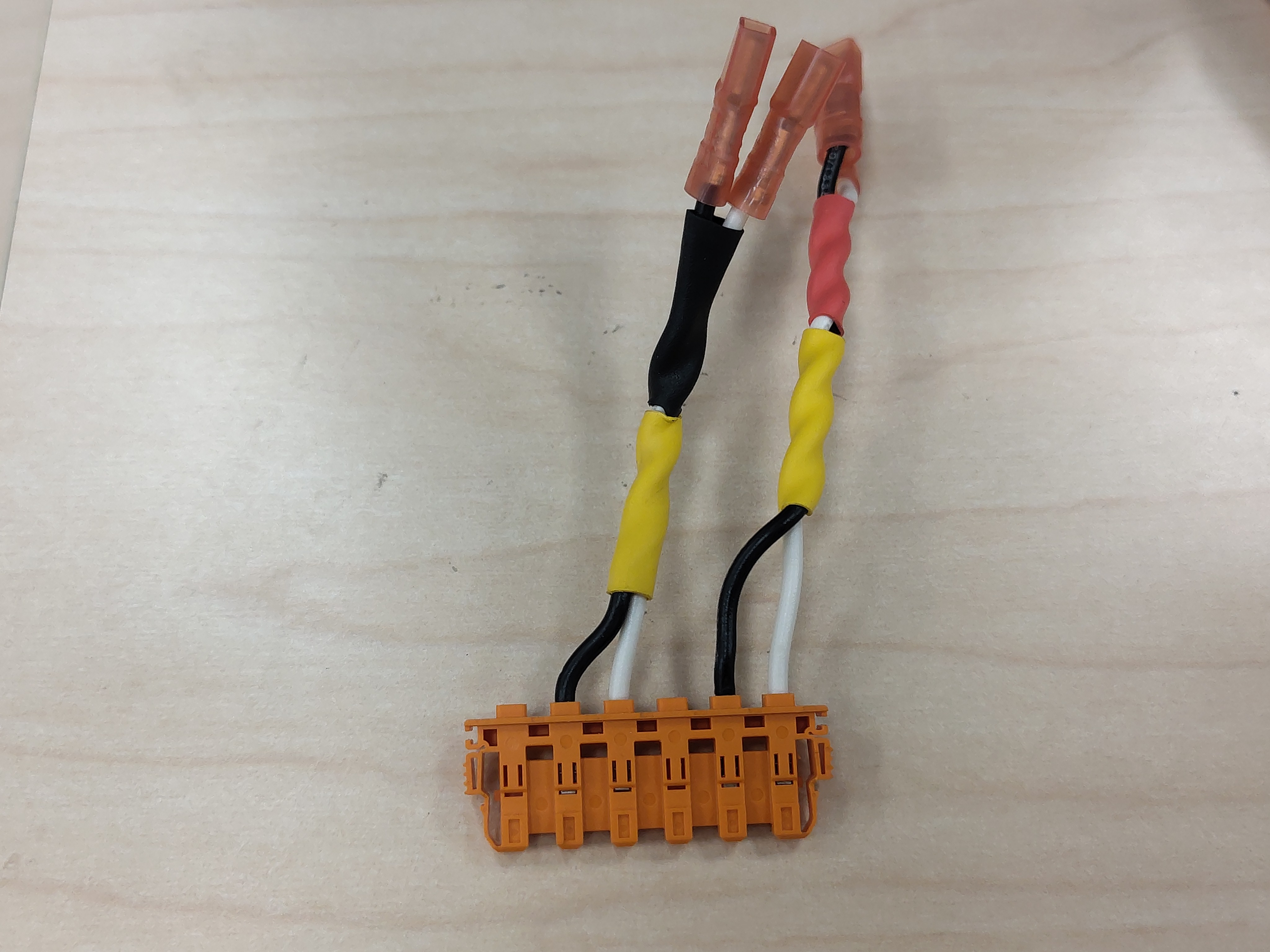
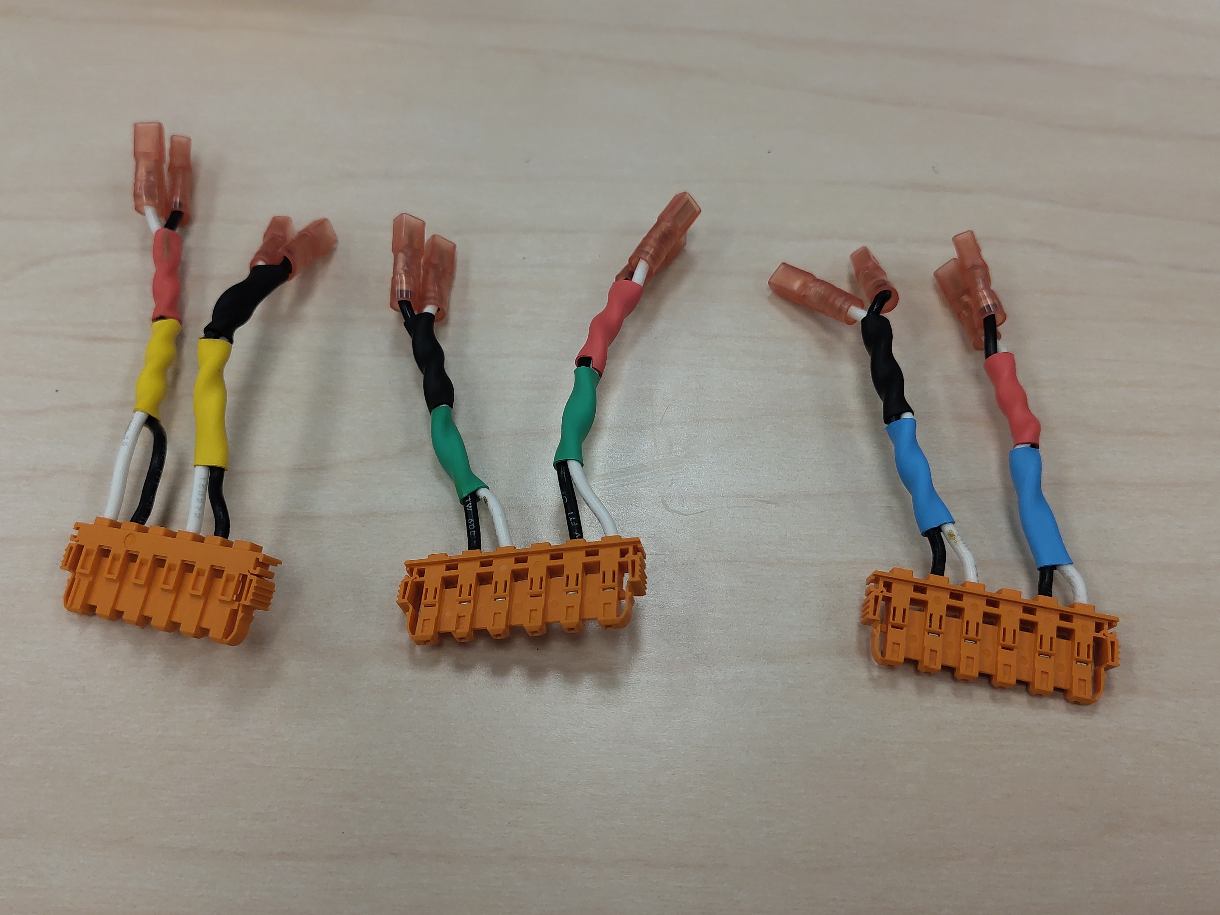
For example, the high-side switch of phase U gets red (side) and yellow (phase), as shown in the photos below. The wire color itself carries the signal identity: white = gate, black = emitter.
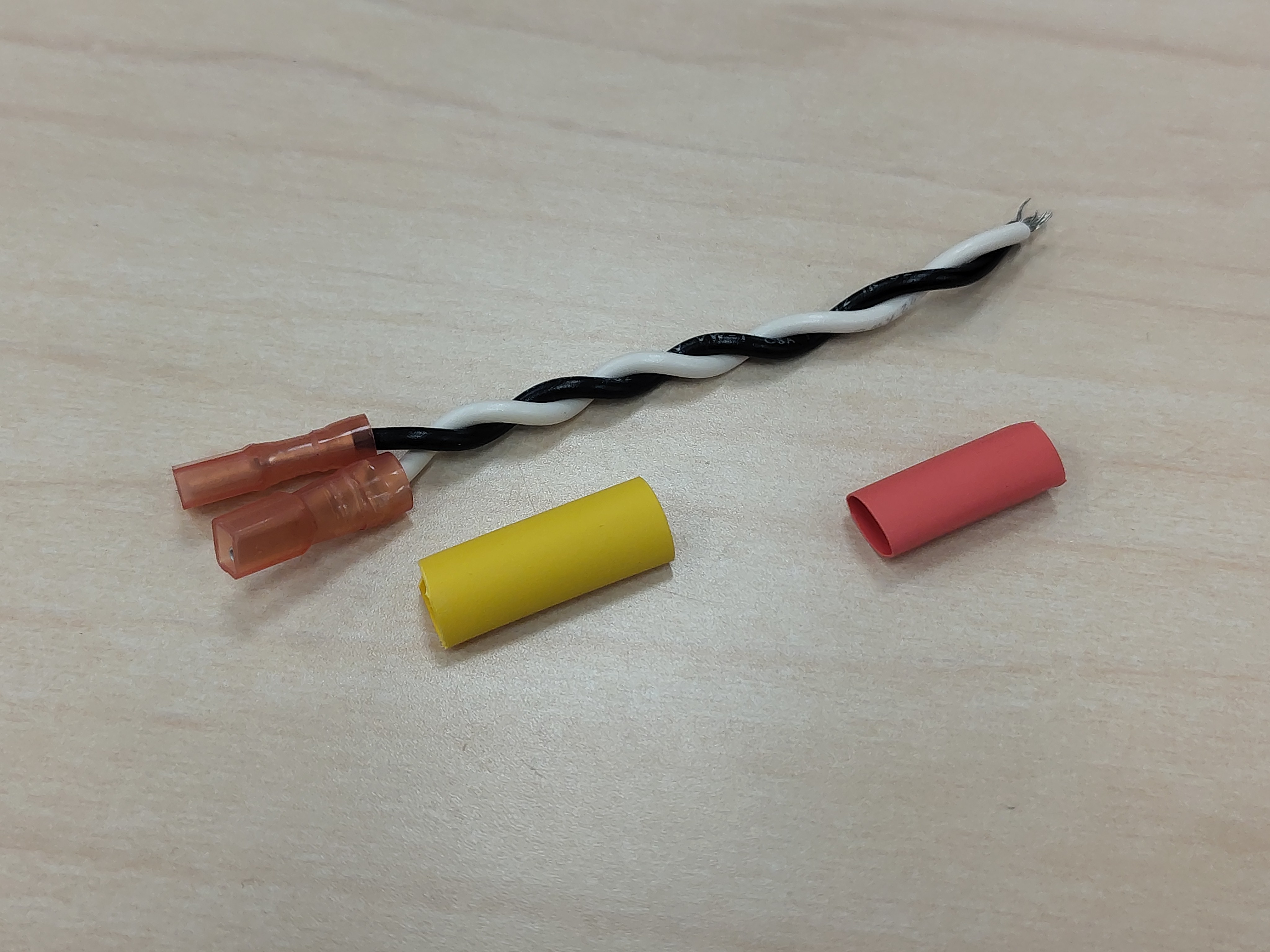
Slide both pieces over the wire end against the terminal bases, leaving a gap between the two terminals so the gate/emitter pair stays easy to identify, then shrink them with a heat gun.
Step 5 - Crimp the TE Connectivity terminals
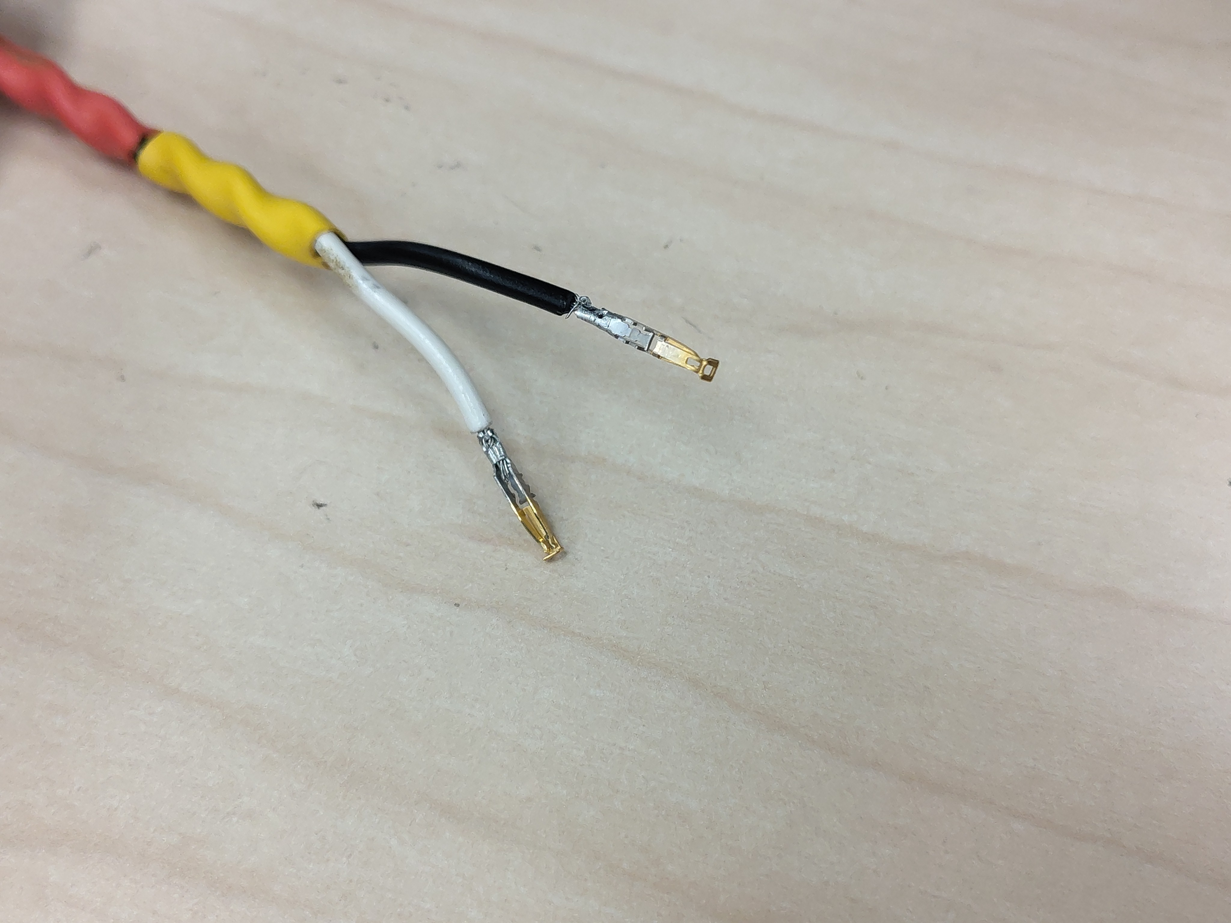
Crimp a TE Connectivity terminal onto each conductor at the other end of the pairs — the end that mates with the gate driver board.
Step 6 - Insert the terminals into the connector housings
Insert the crimped terminals into the orange TE Connectivity connector housings, one housing per phase (yellow = U, green = V, blue = W). Each housing gets that phase's high-side pair and low-side pair — insert into the high-side and low-side gate/emitter positions only. The remaining positions stay open for now.
Important: Do not clip on the connector covers yet. More wiring is added to these housings before they are closed out.
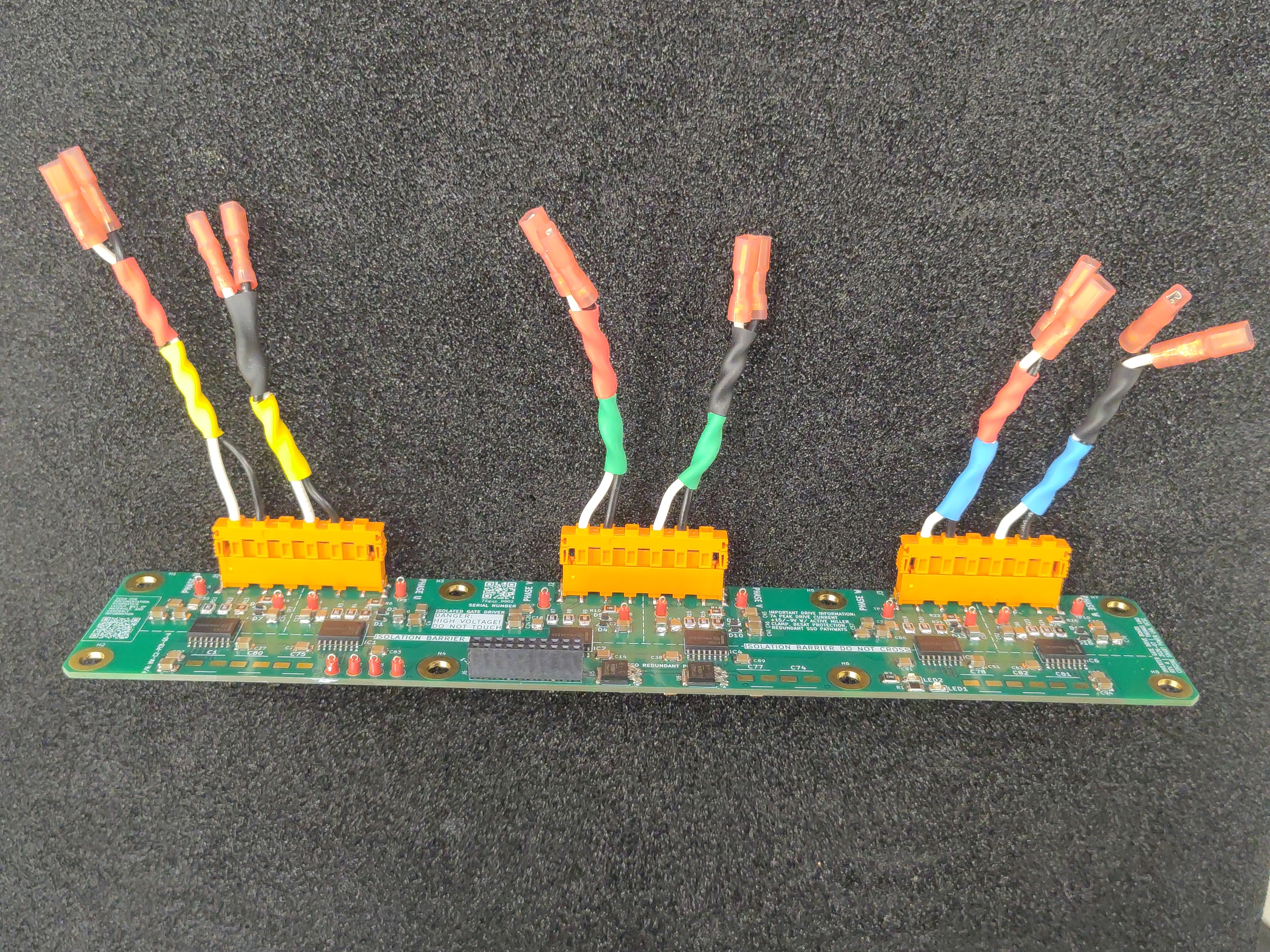
The three housings plug into the gate driver board, one per phase.
Step 7 - Test-fit the gate-emitter pairs on the IGBTs
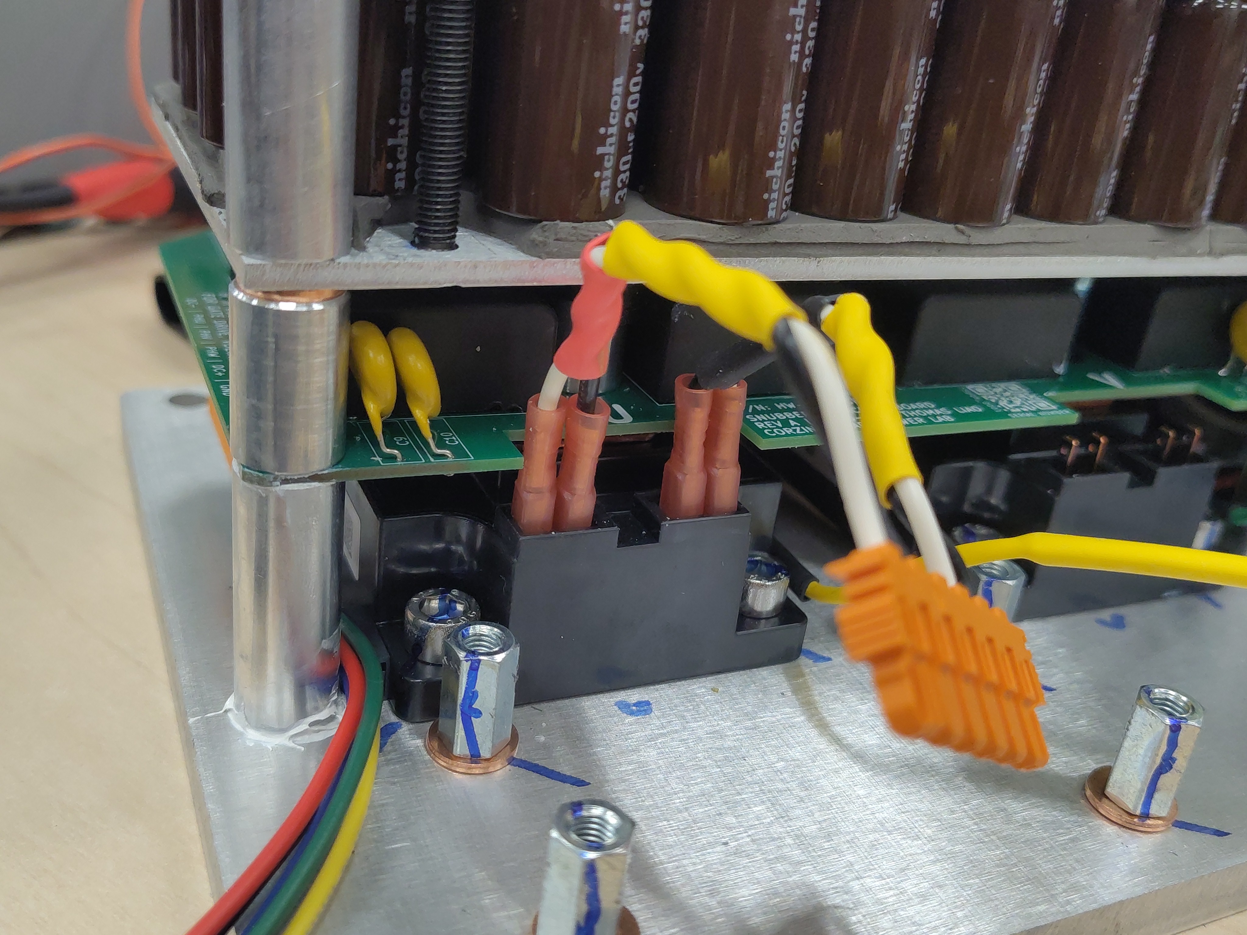
Push the color-coded quick-disconnects onto the gate and emitter pins of each IGBT module to check fit and lead lengths before final routing. The red high-side and black low-side heat-shrink identification makes it easy to keep the pairs straight against the module pinout.
Phase voltage and DC-link sense leads
The second part of the harness carries the phase-voltage (PHU, PHV, PHW) and DC-link (DC+, DC-) sense signals to the gate driver board. These feeds support the desaturation detection and the rest of the voltage sensing on the board. The gate driver board silkscreens the housing positions: DC- | PHU | PHV | PHW | DC+ | GND.
Step 8 - Cut the sense leads
Cut one lead per signal, in the same colors as the phase code: yellow = PHU, green = PHV, blue = PHW, red = DC+, black = DC-.
Step 9 - Crimp and insert the sense leads
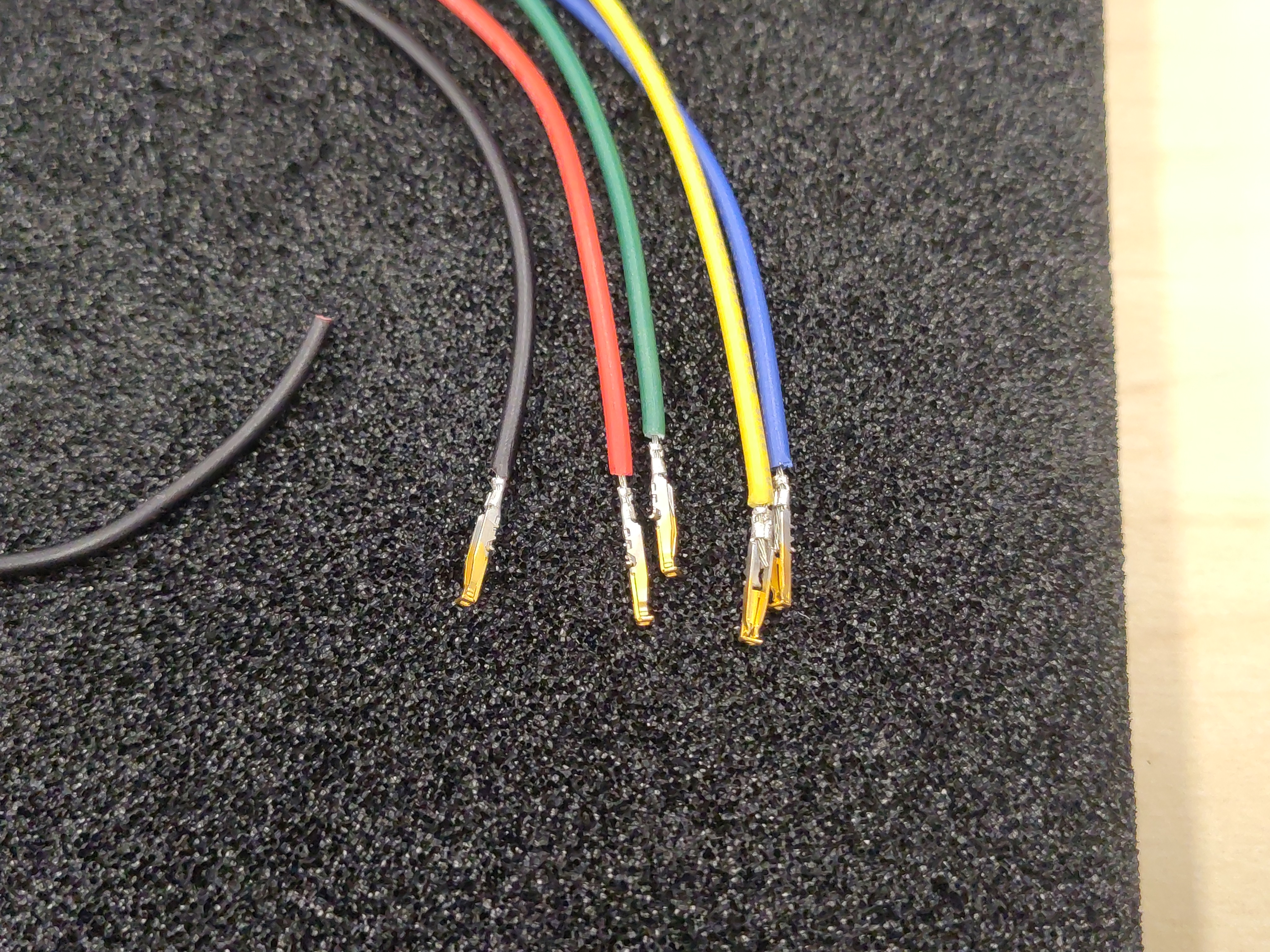
Crimp a TE Connectivity terminal onto each sense lead and insert the leads into the 6-position orange housing, in the order silkscreened on the board: DC-, PHU, PHV, PHW, DC+ (GND stays open for now).
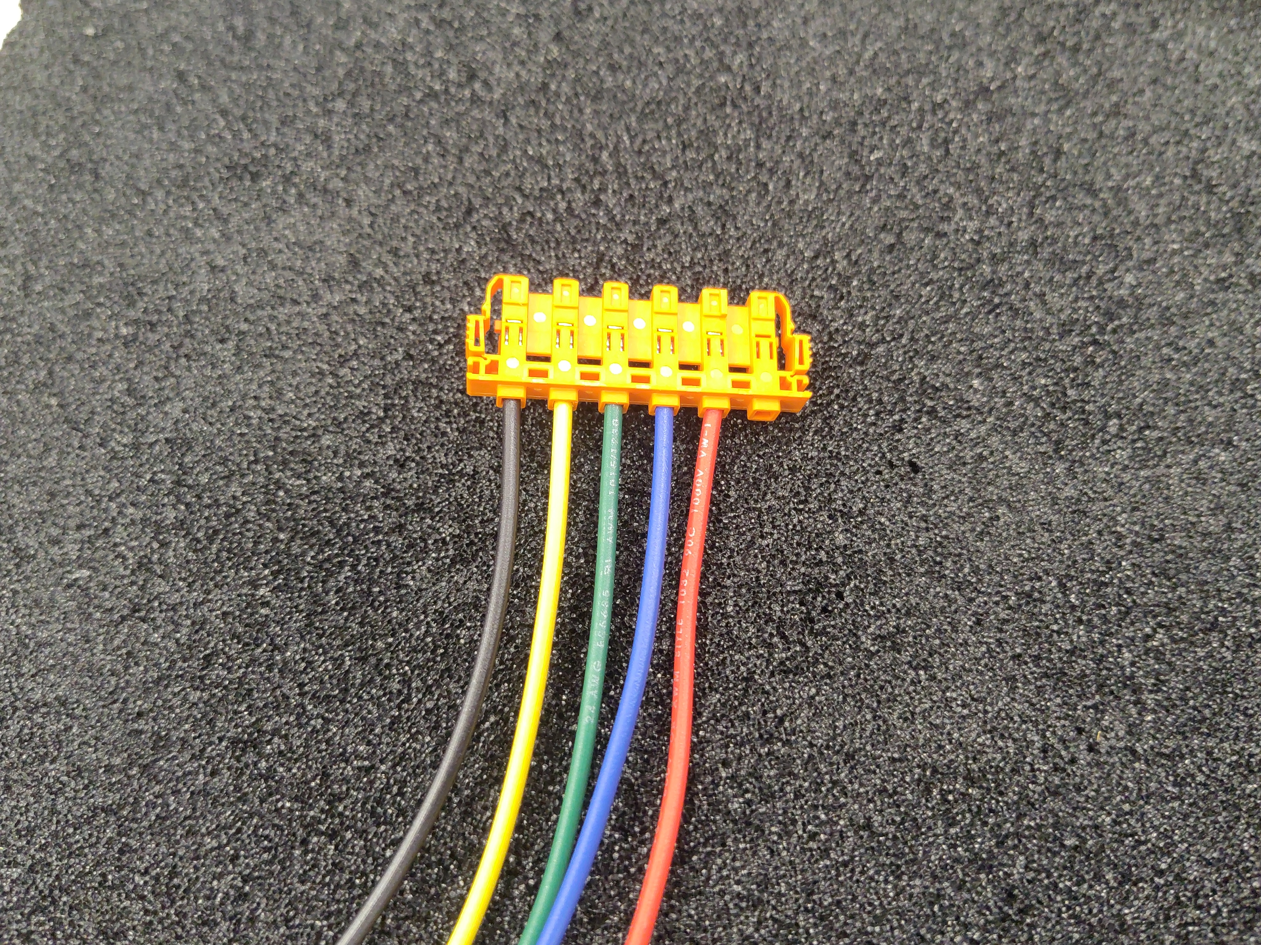
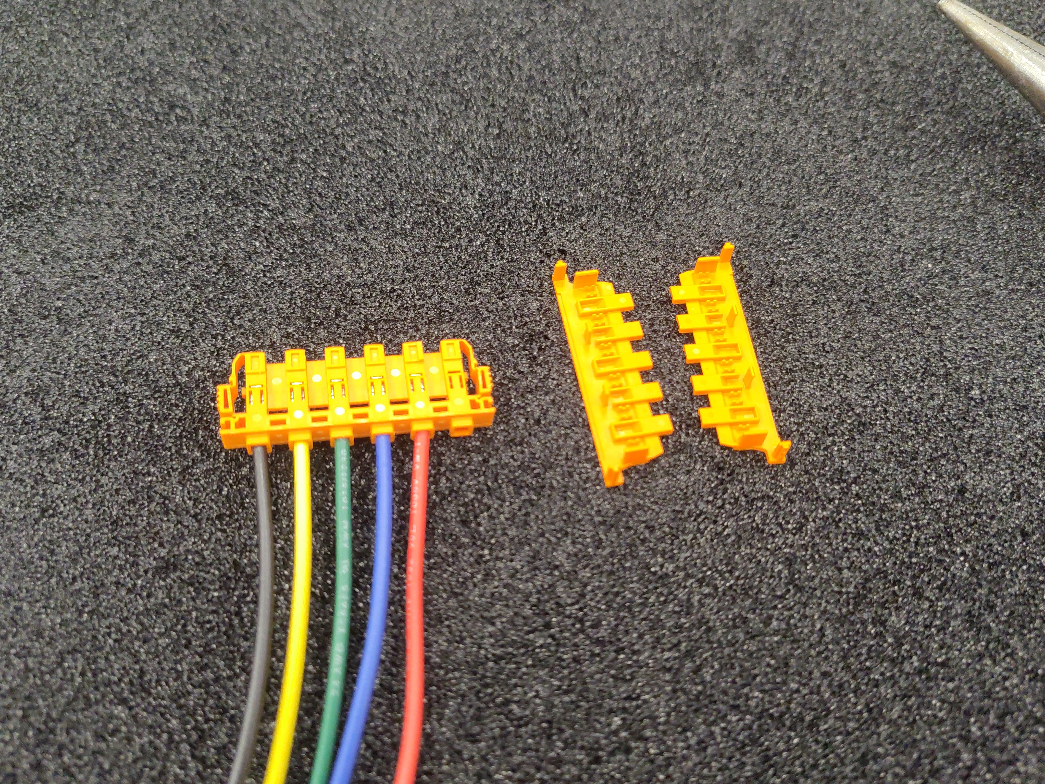
Important: Do not clip on the connector covers yet. The desaturation leads are added to this housing later.
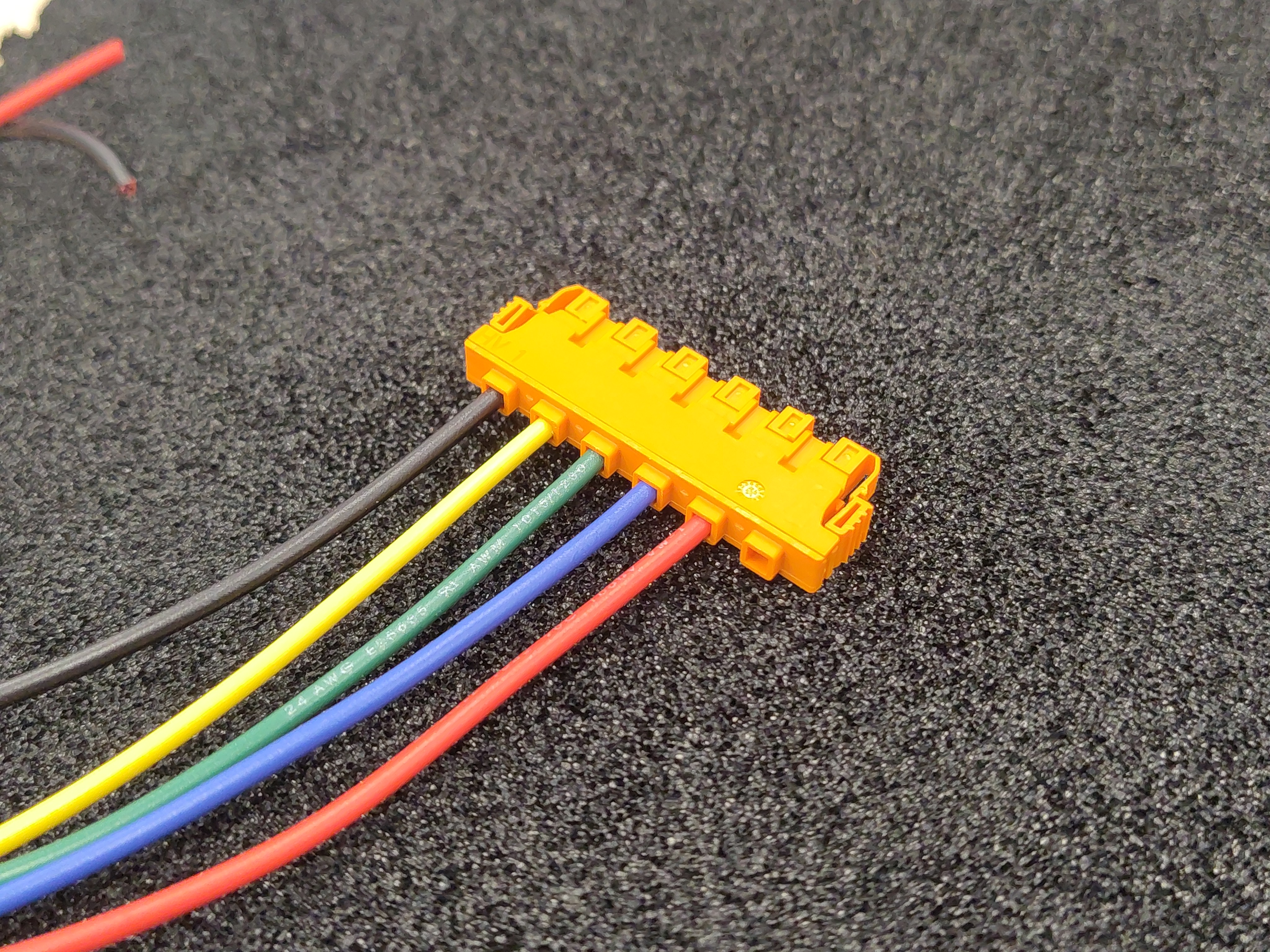
Step 10 - Plug the sense housing into the gate driver board
Mate the housing into the board position labeled for gate drive and voltage sense, following the silkscreen legend.
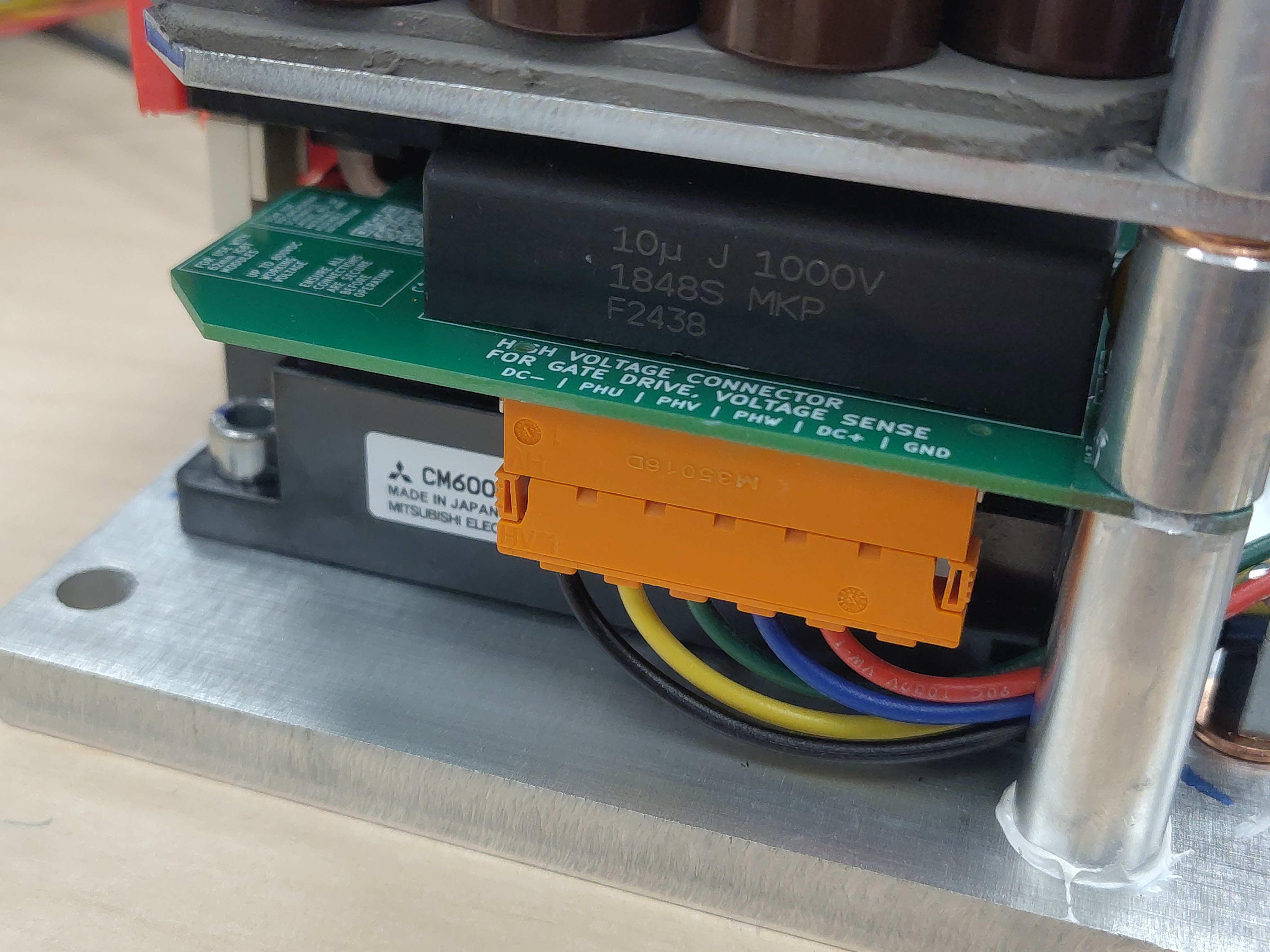
Final assembly
With all six gate-emitter pairs built and color-coded, the set should cover:
- High-side U (red + yellow), V (red + green), W (red + blue)
- Low-side U (black + yellow), V (black + green), W (black + blue)
The other end of each pair terminates in a TE Connectivity terminal inserted into that phase's orange connector housing on the gate driver board. The connector covers are not clipped on yet; more wiring is added to these housings first.
Next steps
Still to come: the gate-emitter pairs fitted to all three IGBT modules, the voltage-sense leads run to the phase outputs and DC link, the desaturation leads, and the final splices. The connector covers stay off until the housings are fully populated.