
OV-C2-AG-04-PCB · v0.2 · 2026-08-14
| Doctype | Assembly Guide |
|---|---|
| Doc id | OV-C2-AG-04-PCB |
| Product line | openvvvf |
| Applies to | chassis-size-2 |
| Version | 0.2 |
| Date | 2026-08-14 |
| Description | Populate and solder the DC-link capacitor PCB for the Chassis Size 2 power stage. |
| Nav order | 227 |
| Normative refs | OV-C2-IG-INDEX |
DC-Link Capacitor Board Assembly
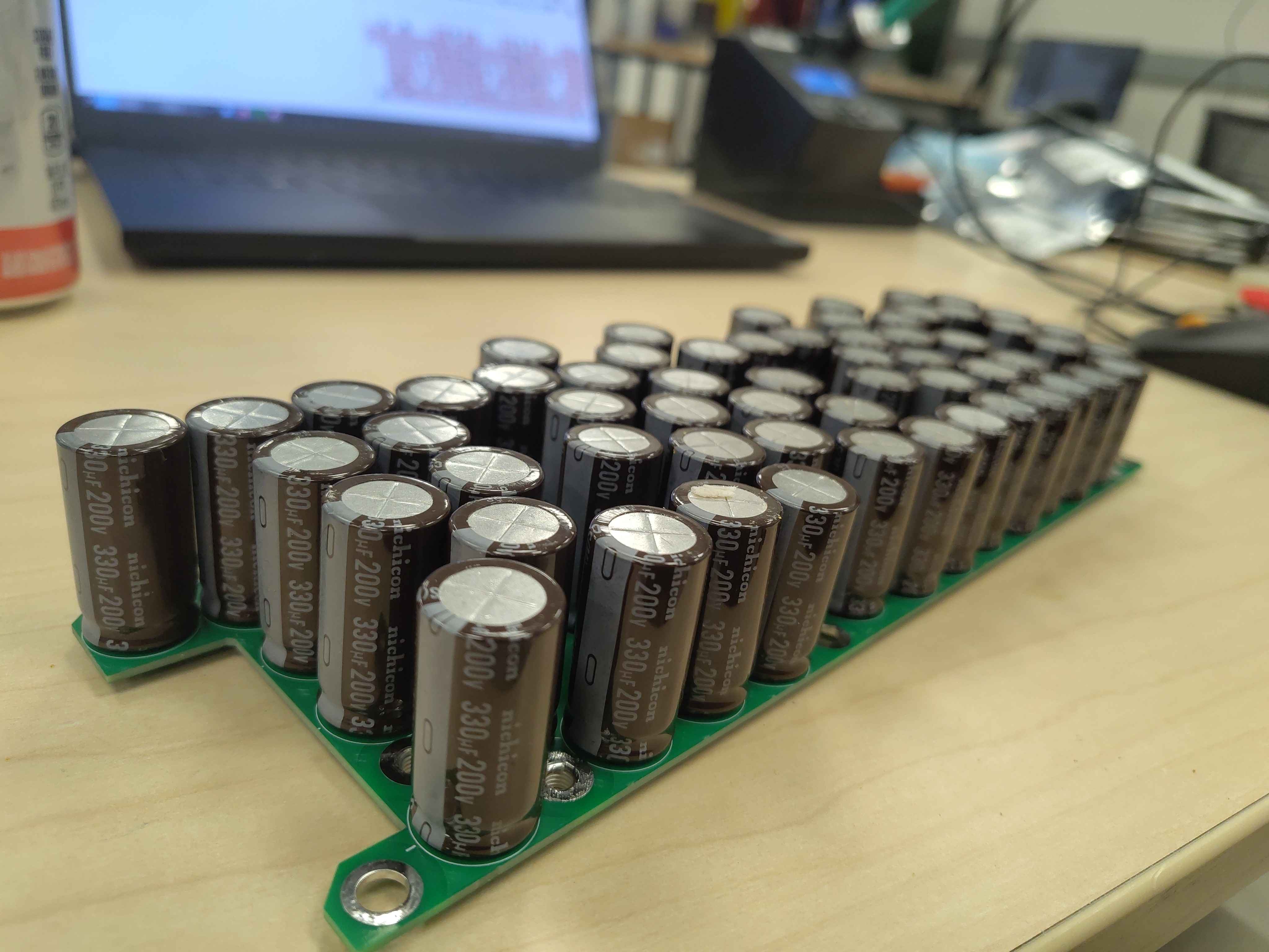
This guide covers populating the DC-bus capacitor PCB (DCBusCapacitorBoard) used in the Chassis Size 2 DC-link module. The board carries 60 electrolytic capacitors that make up the DC-link energy storage, plus threaded standoffs for mounting to the chassis later.
Safety
- This board operates at high DC voltage. Treat it as energized until proven discharged, even when disconnected from the inverter.
- Wear safety glasses when cutting leads; clipped capacitor legs can fly off at high speed.
- Use a temperature-controlled soldering iron and adequate ventilation or fume extraction.
- Confirm correct capacitor polarity before soldering; reversed electrolytic capacitors can vent or burst when powered.
Required materials and tools
| Item | Qty | Notes |
|---|---|---|
DC-bus capacitor PCB (HW-C2-PCB-DCBUSCAP-A) |
1 | Chassis Size 2 |
| Nichicon UCS2D331MHD electrolytic capacitor | 60 | 330 µF, 200 V radial leaded |
| M5 threaded steel standoff | 8 | For top-case mounting |
| Solder | as needed | Leaded or lead-free, flux-core |
| Flux | as needed | No-clean or water-washable |
| Temperature-controlled soldering iron with a large chisel tip | 1 | High thermal mass needed for copper planes and M5 standoff pads |
| Lead cutters / flush cutters | 1 | For trimming capacitor leads |
| ESD-safe tweezers or gloves | 1 | To handle parts cleanly |
| Permanent marker | 1 | For variant mark |
| Lint-free wipes and isopropyl alcohol | as needed | For flux cleanup |
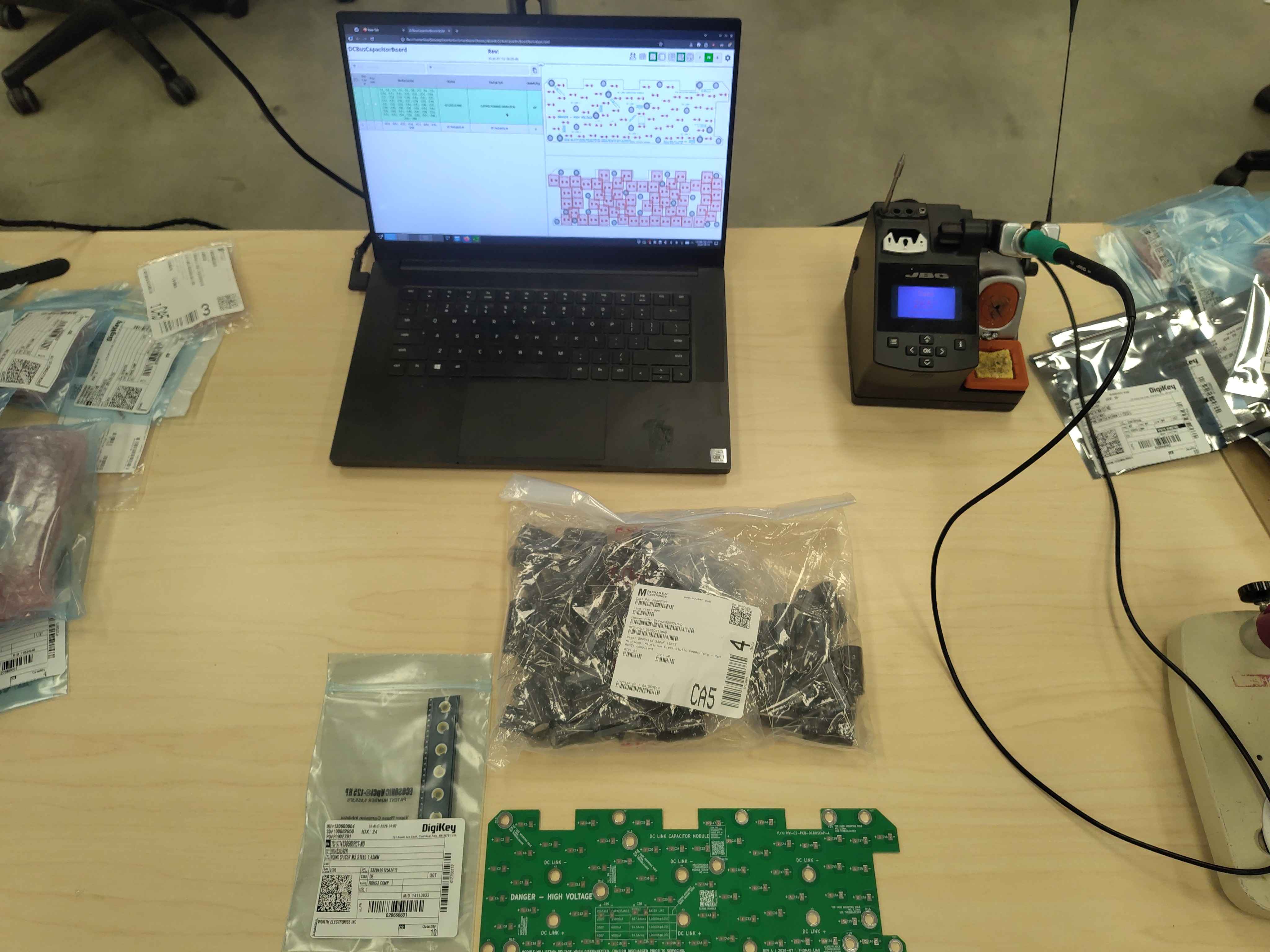
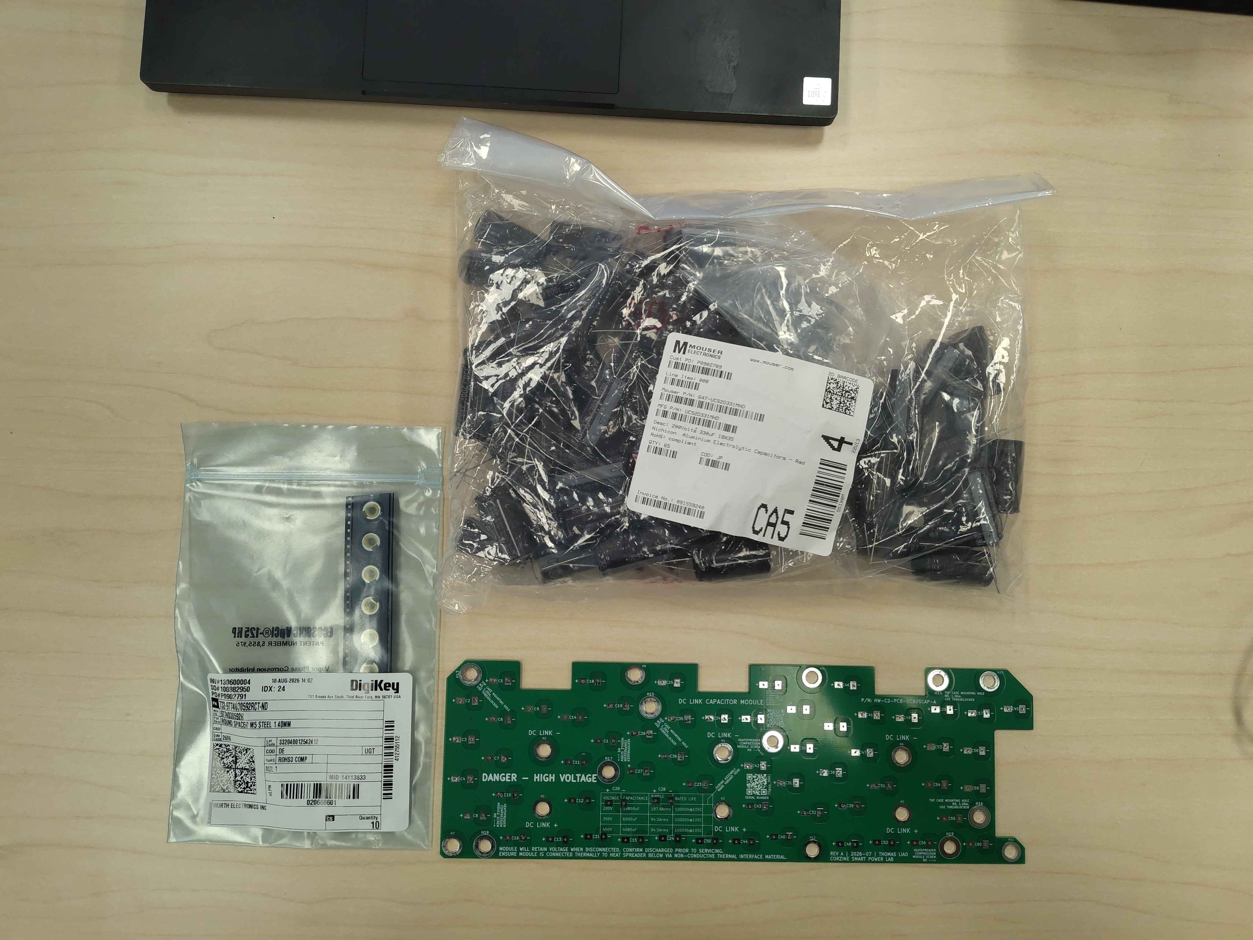
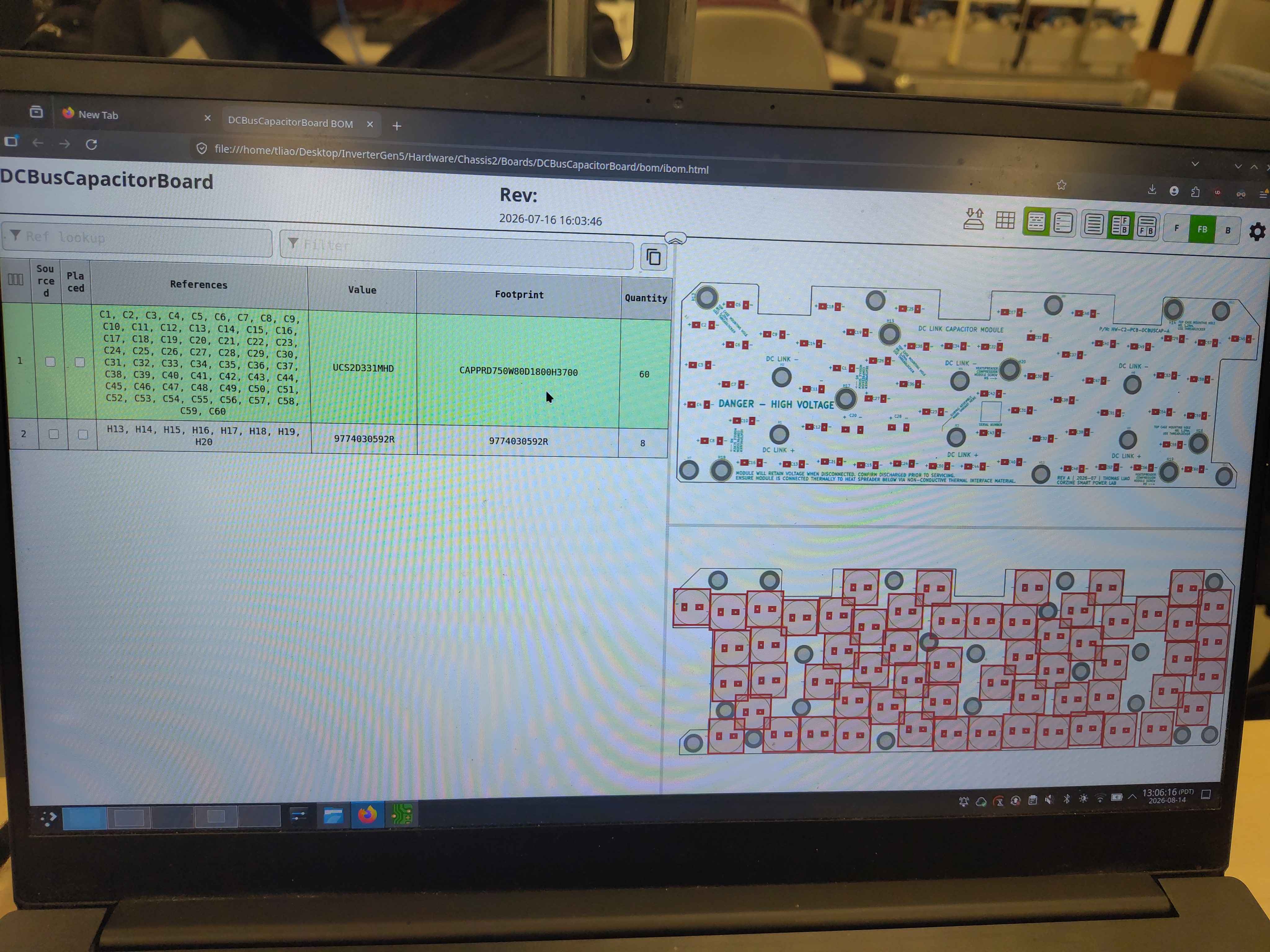
Step 1 - Install the M5 threaded standoffs
Start by installing the eight M5 threaded standoffs. The standoffs ship with protective tape pre-applied, which helps keep the threads and mounting face clean during soldering. Insert a standoff into each mounting hole from the component side, keep it perpendicular to the board, and solder the standoff body to the large PCB pad on the solder side.
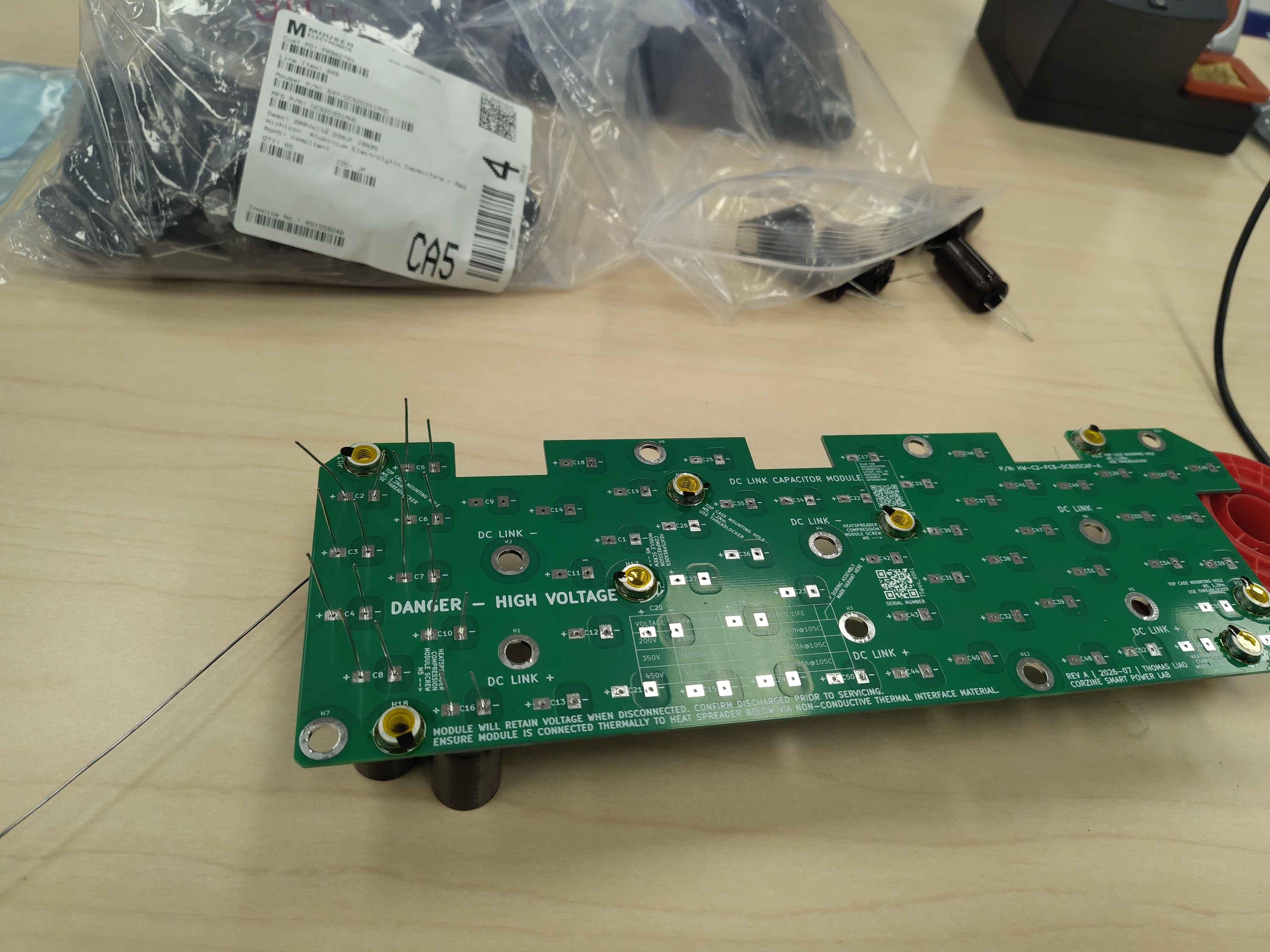
Tip: Leave the pre-applied tape in place until the very end of assembly; it protects the standoff threads and solder pad area during handling and cleaning.
Step 2 - Insert all capacitors
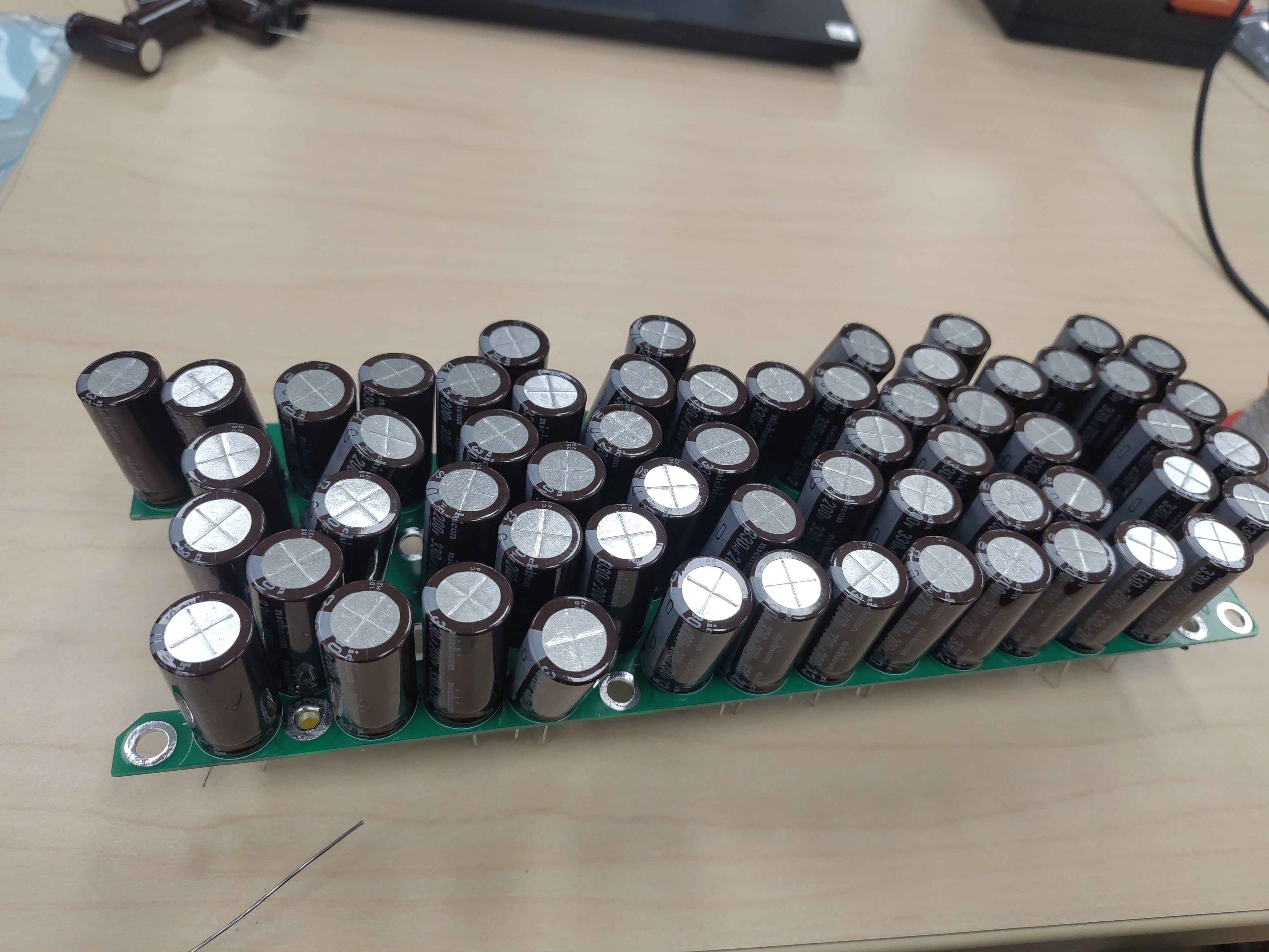
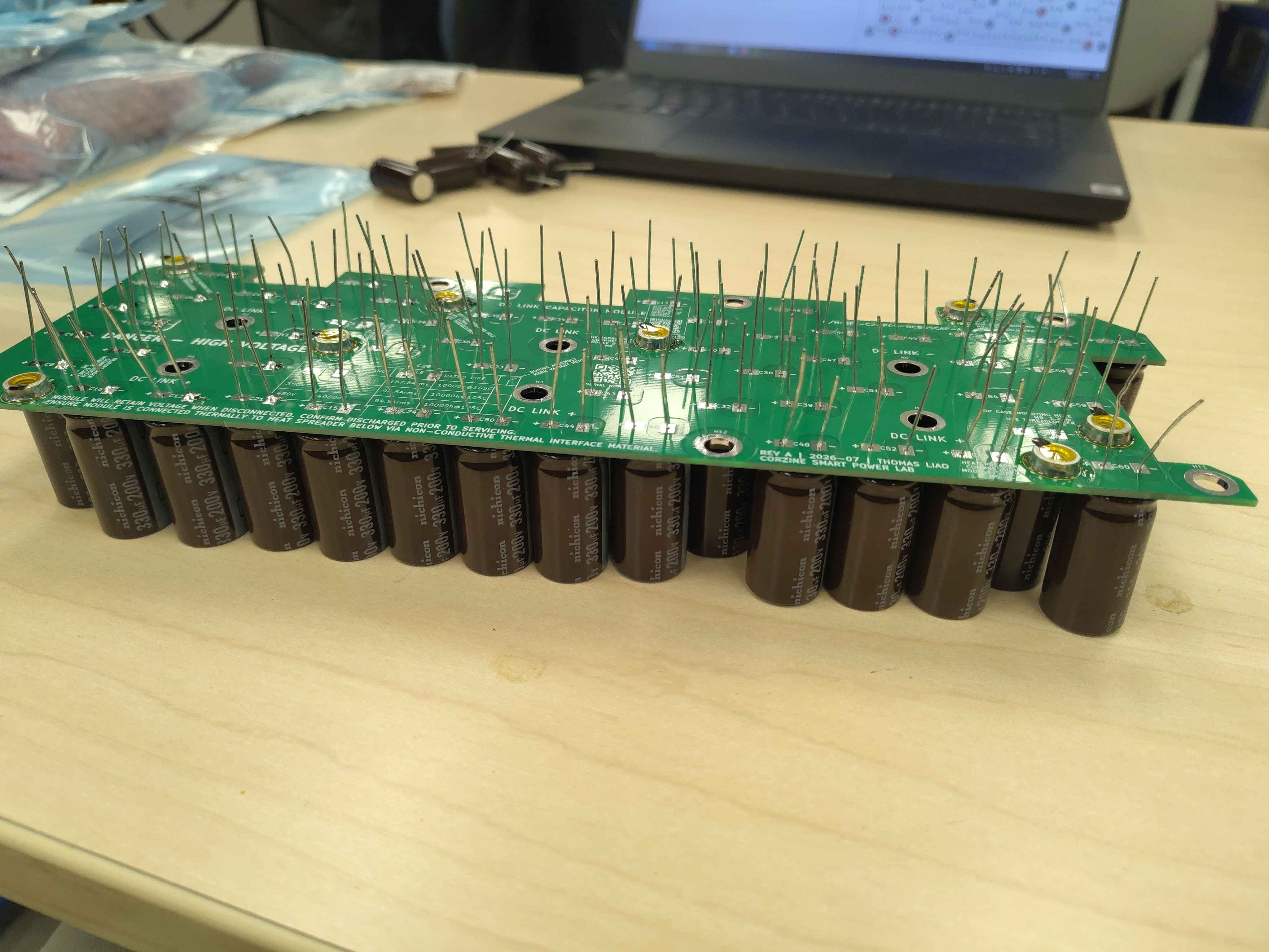
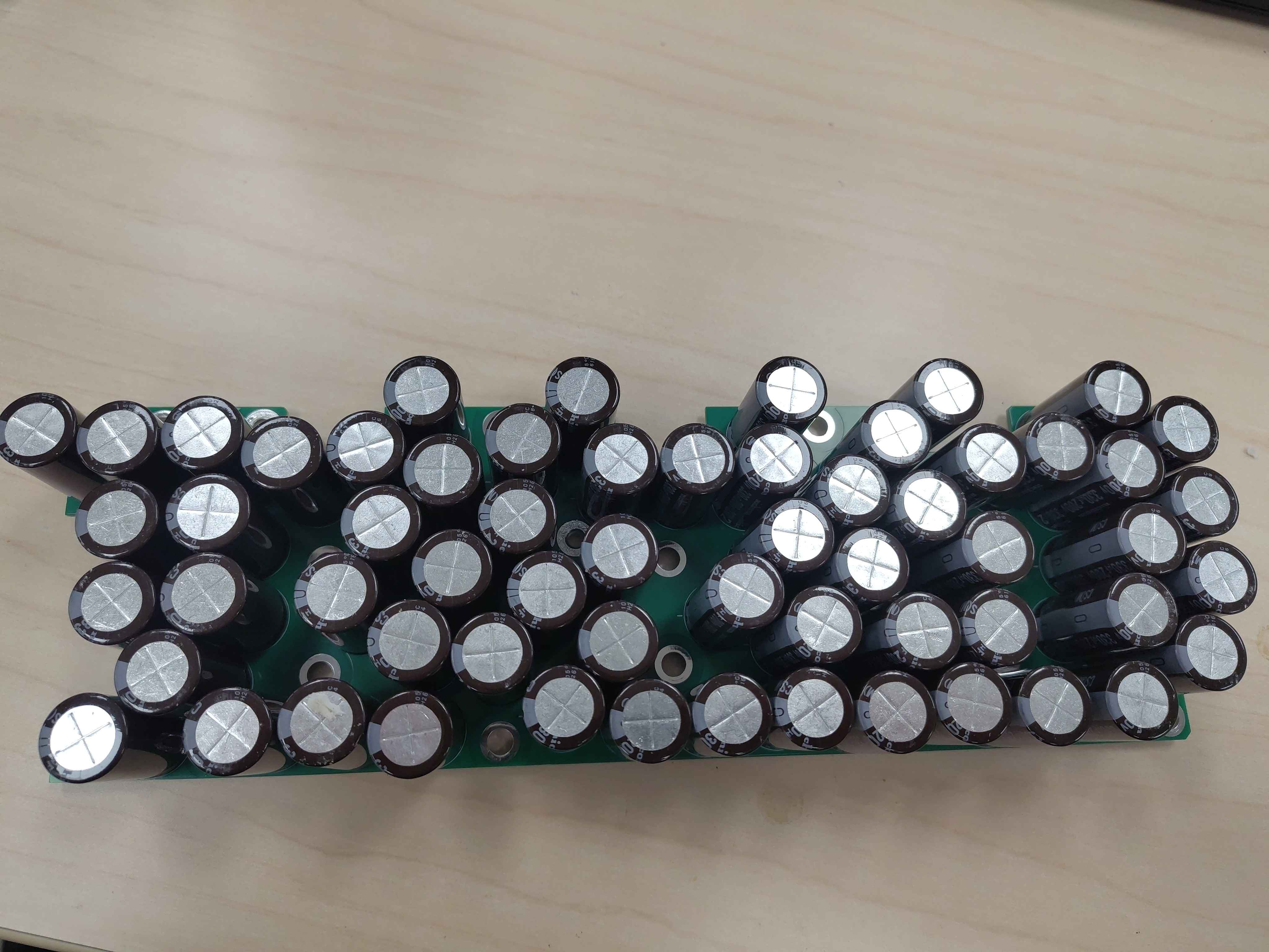
Insert the 60 electrolytic capacitors into their respective positions. The capacitors have a stripe on the negative side and the longer lead is positive. Each PCB position is marked with + and – polarity indicators, so insert each capacitor with the stripe toward – and the longer lead through +.
Step 3 - Verify capacitor orientation a second time
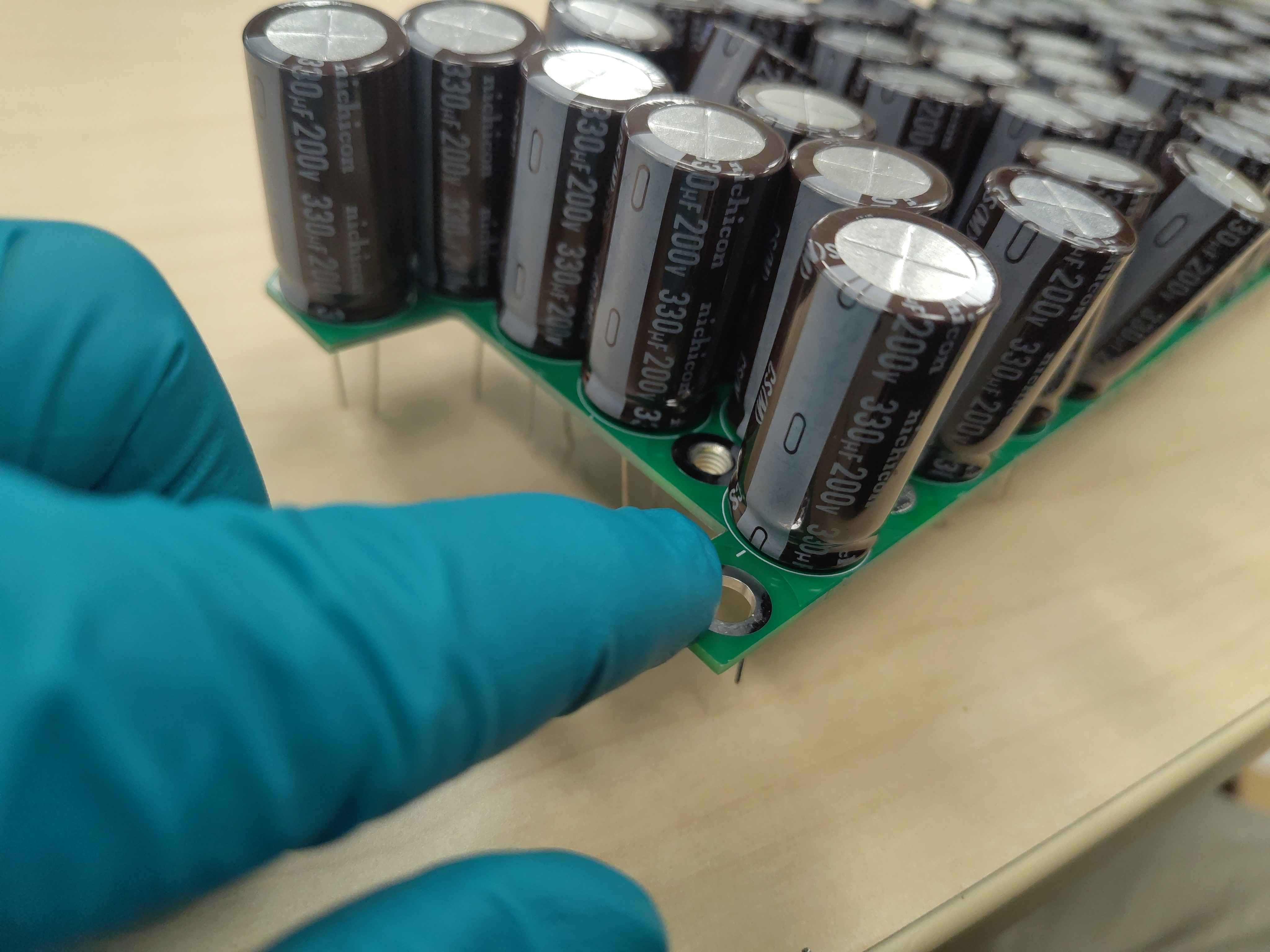
Before soldering anything, go over every capacitor again and double-check its polarity against the silkscreen. A single reversed capacitor on a high-voltage DC link can fail catastrophically when powered.
Step 4 - Seat the capacitors fully
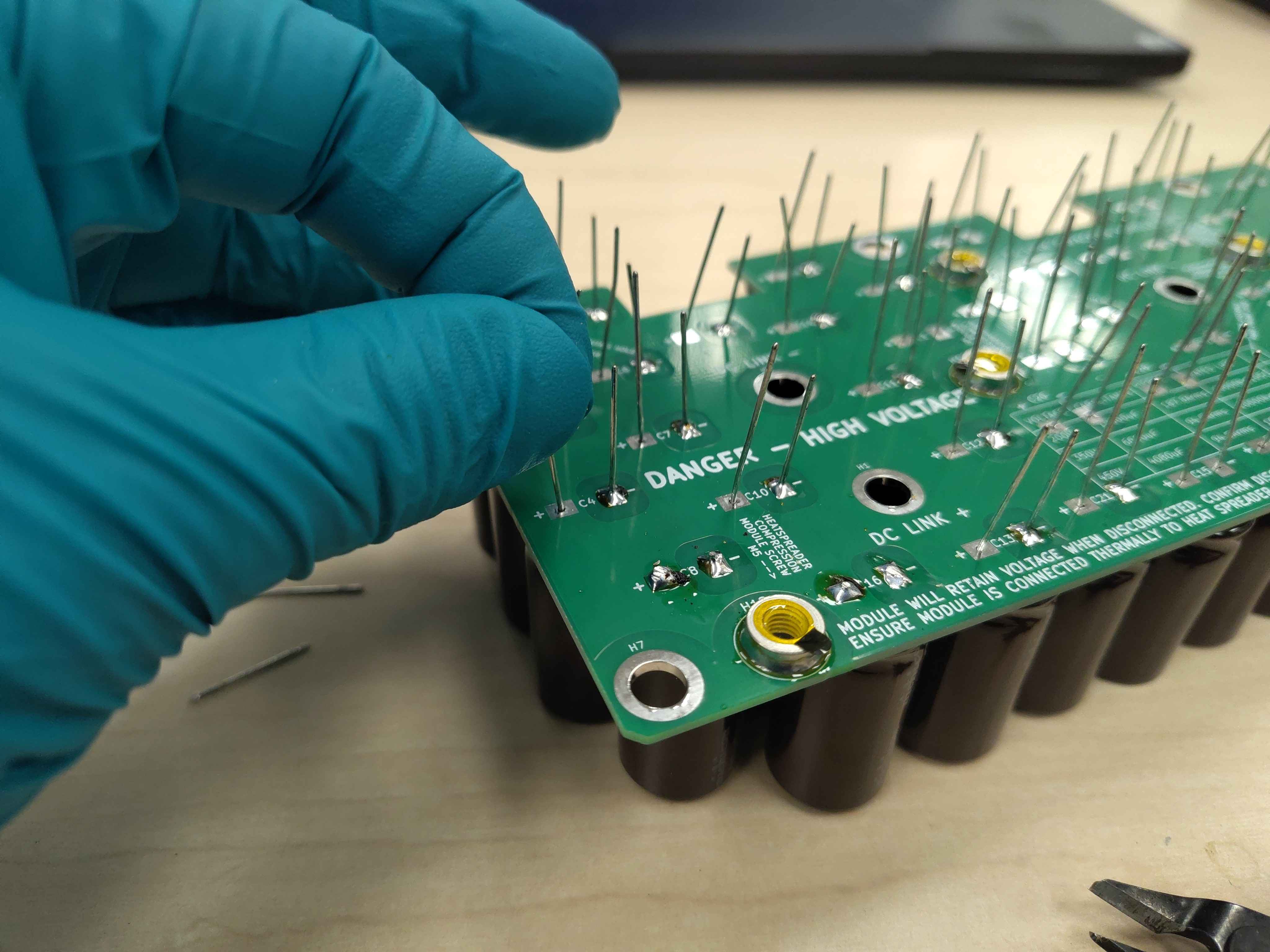
From the solder side, grip the leads of each capacitor and pull gently while pressing the capacitor body against the board from the component side. This ensures the capacitors sit flat and the leads are exposed far enough for reliable soldering.
Step 5 - Tack solder each capacitor
To keep the capacitors from shifting, solder one lead of each capacitor first. A single tack joint per capacitor is enough to lock the part in place; the remaining lead is soldered in the next step.
Tip: Work on one lead polarity at a time — for example, tack all the negative leads first, moving across the board in one direction, then repeat with the positive leads. Keep the capacitor bodies resting on the bench so they stay fully seated and do not fall out when the solder melts.
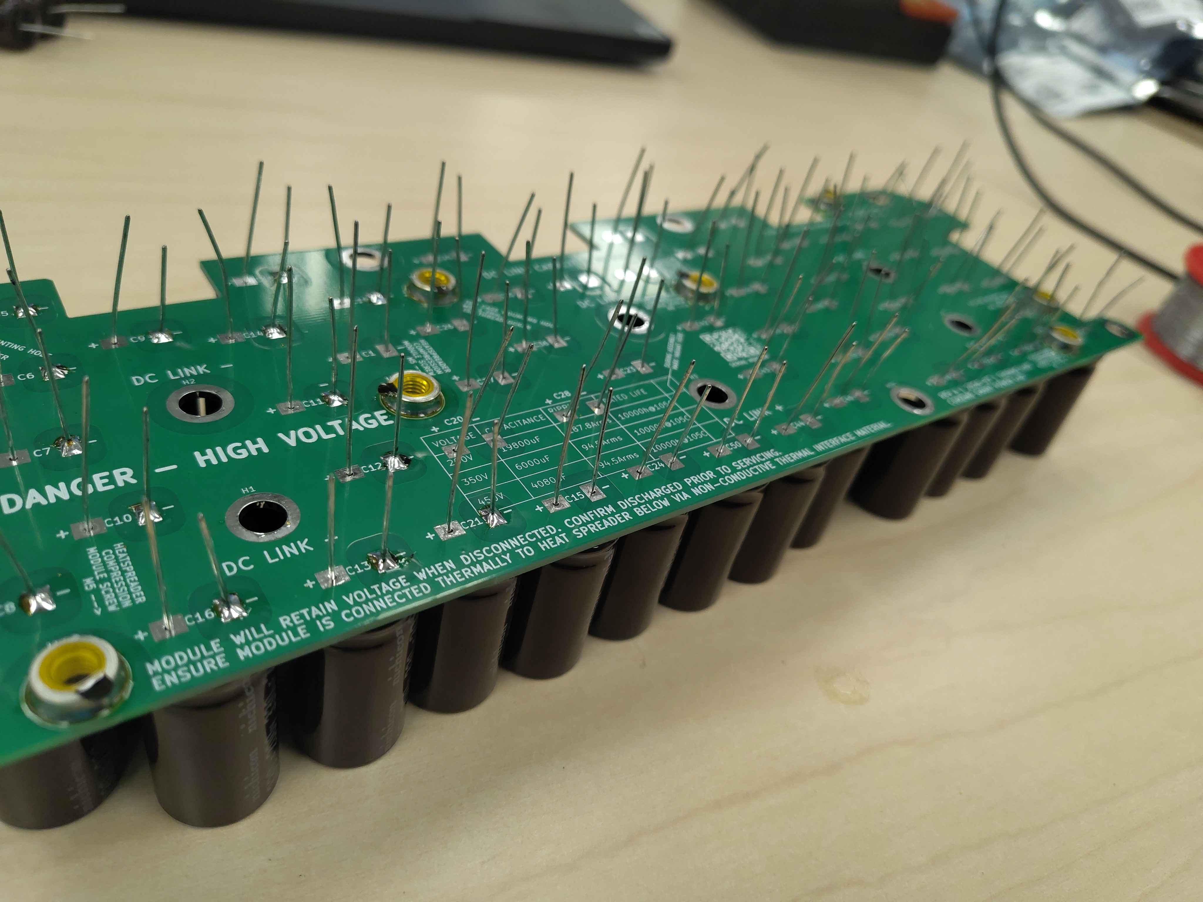
Step 6 - Solder all capacitor leads
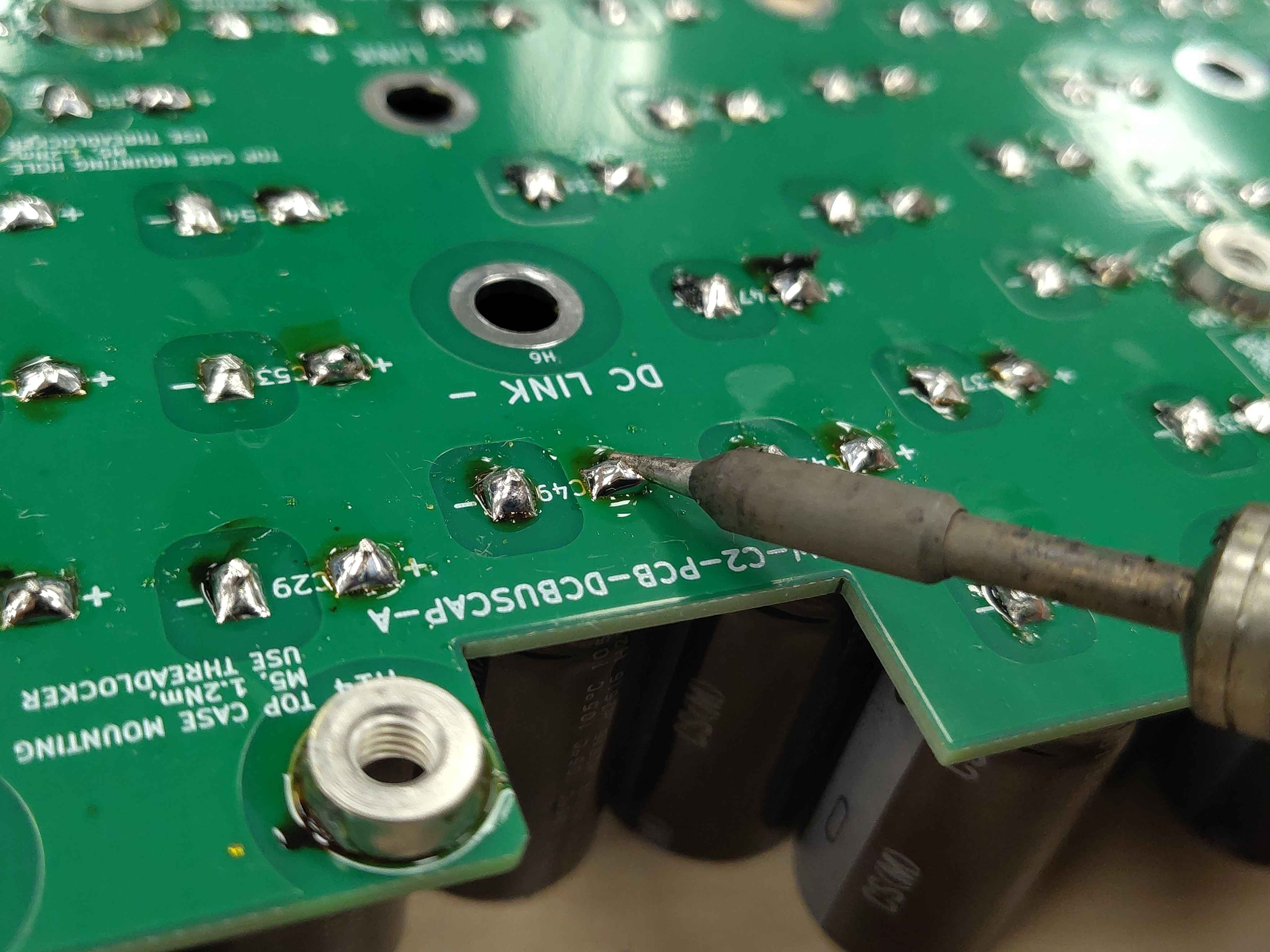
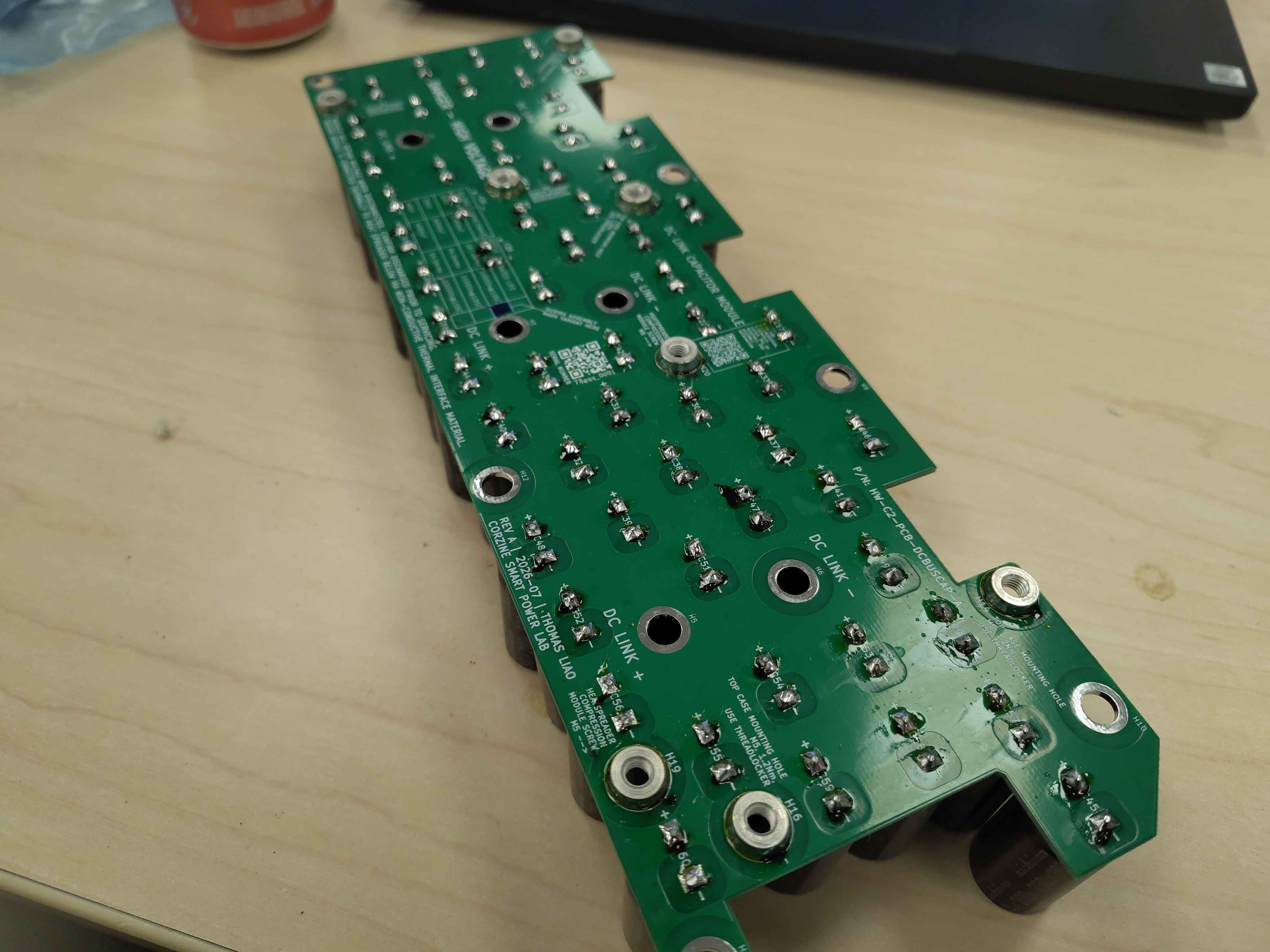
Solder the second lead of every capacitor. Aim for a shiny, concave fillet that completely wets both the lead and the pad. Avoid cold joints, solder bridges between adjacent pads, and excessive solder that could short to nearby pads.
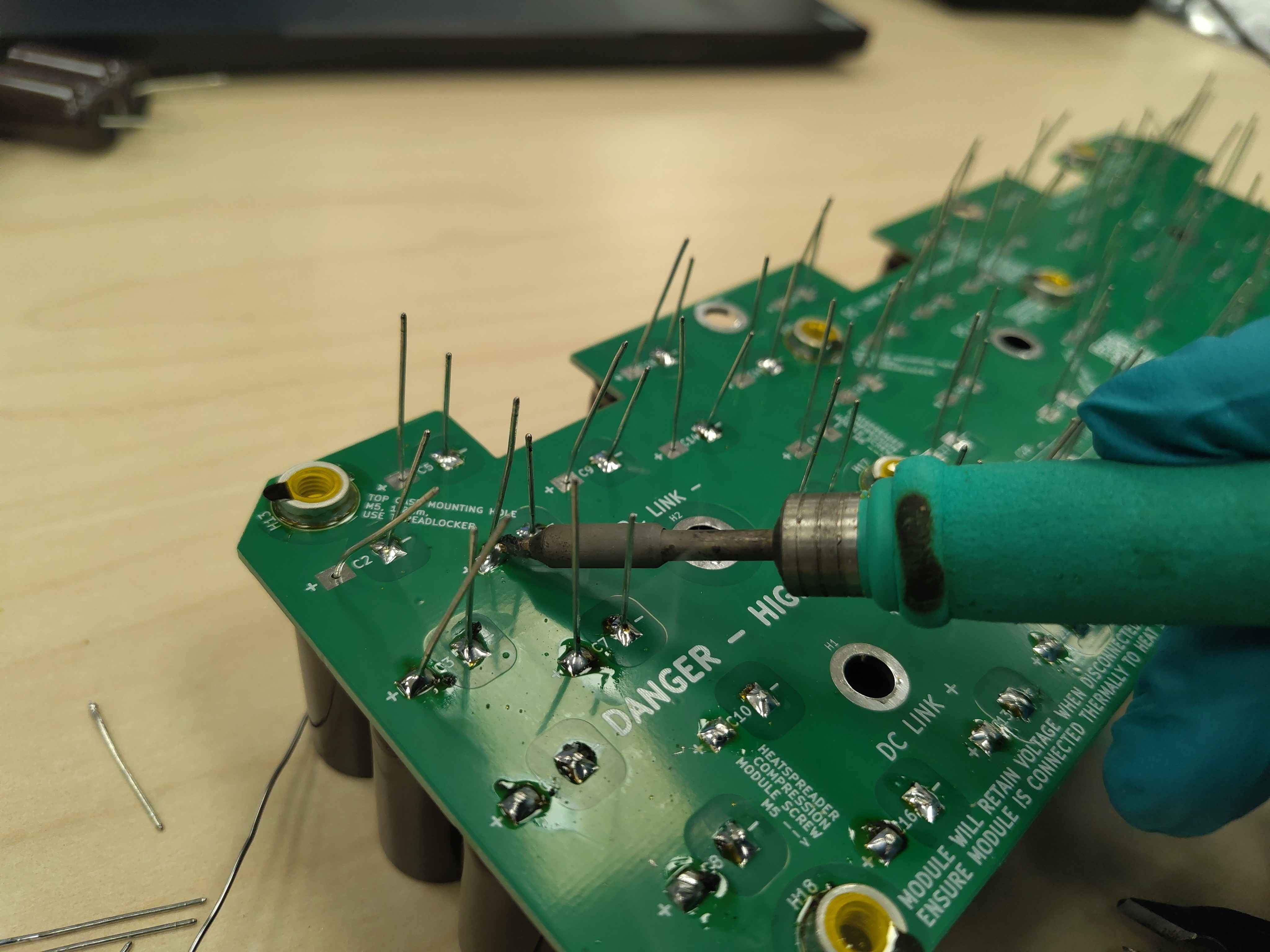
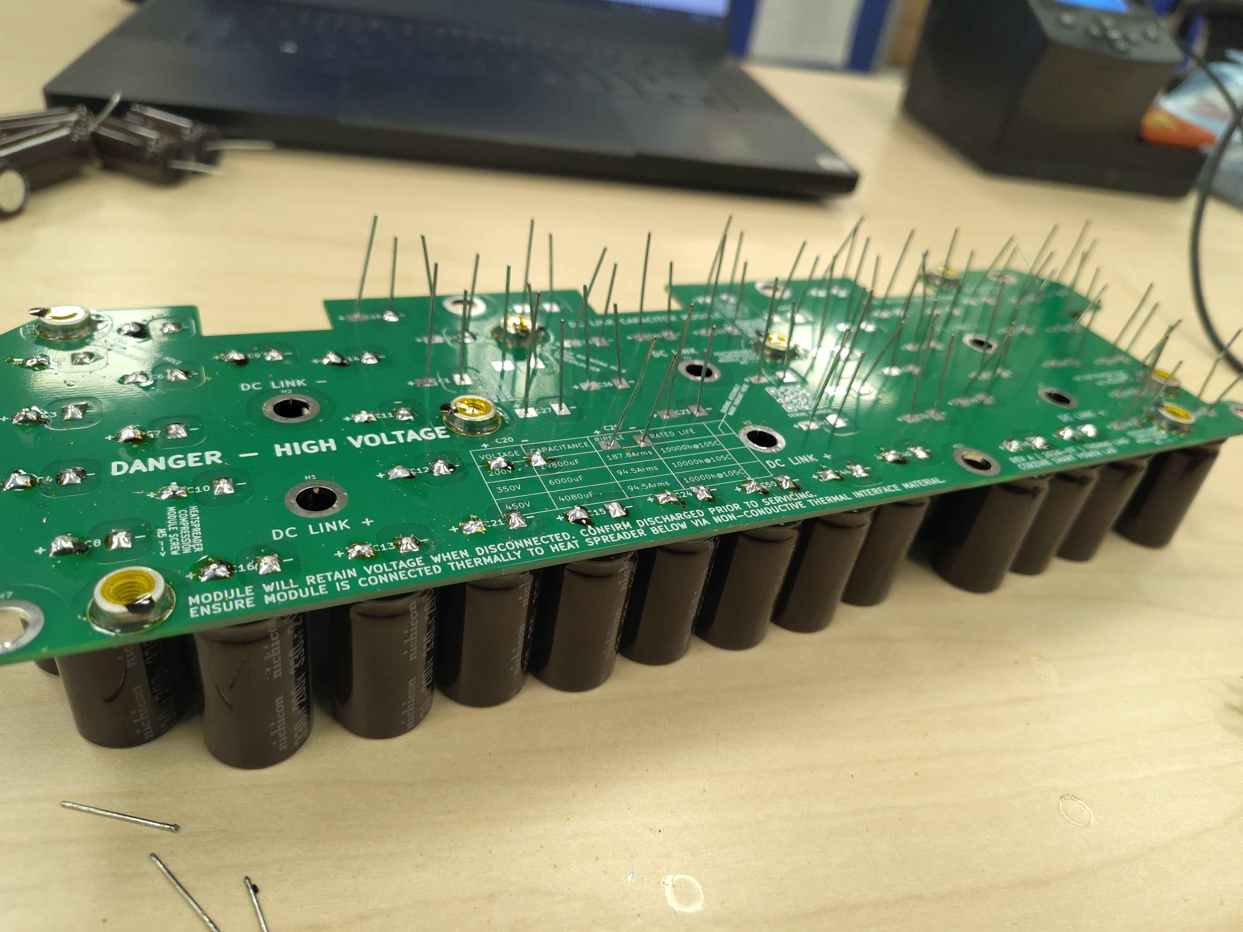
Step 7 - Trim and reflow the leads
Trim each capacitor lead close to the solder joint with flush cutters, then immediately reflow the solder with the iron for a moment to heal any micro-fractures caused by the mechanical shock. Do not trim the leads before soldering — it is too easy to cut them too short, leaving insufficient lead to form a reliable joint.
Tip: Reflow one polarity at a time, working across the board in one direction before switching to the other leg. Keep the capacitor bodies resting on the bench so they remain fully seated and do not drop out when the joint is reheated.
Leave a smooth solder dome with no sharp protrusions, and collect the clipped leads so they cannot short against the board or other assemblies.
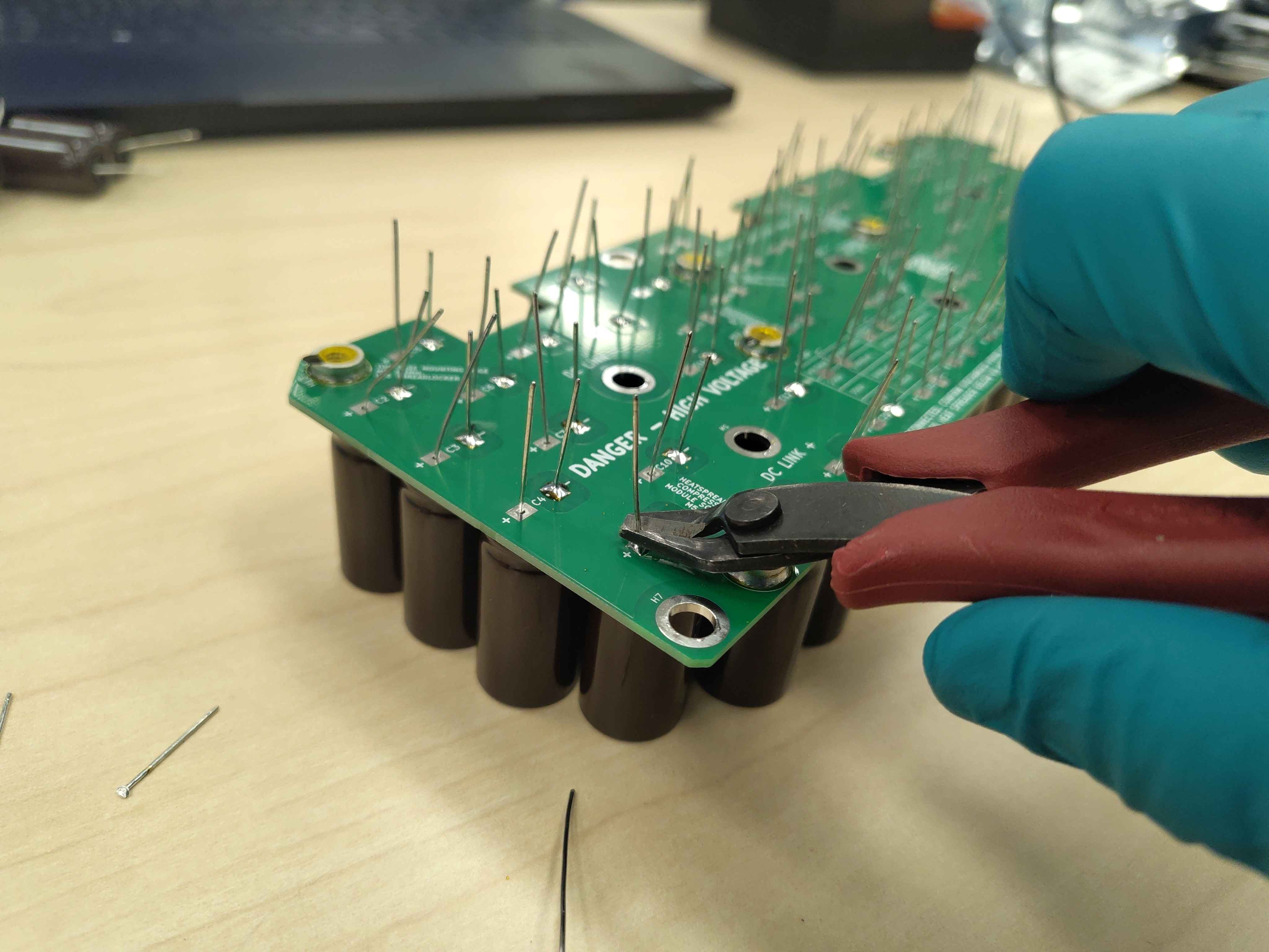
Step 8 - Clean the flux residue
Wipe the solder side of the board with lint-free wipes and isopropyl alcohol to remove flux residue. Do not use an ultrasonic cleaner on this assembly — the vibrations can damage the internal welds and seals of aluminum electrolytic capacitors.
Step 9 - Mark the board variant
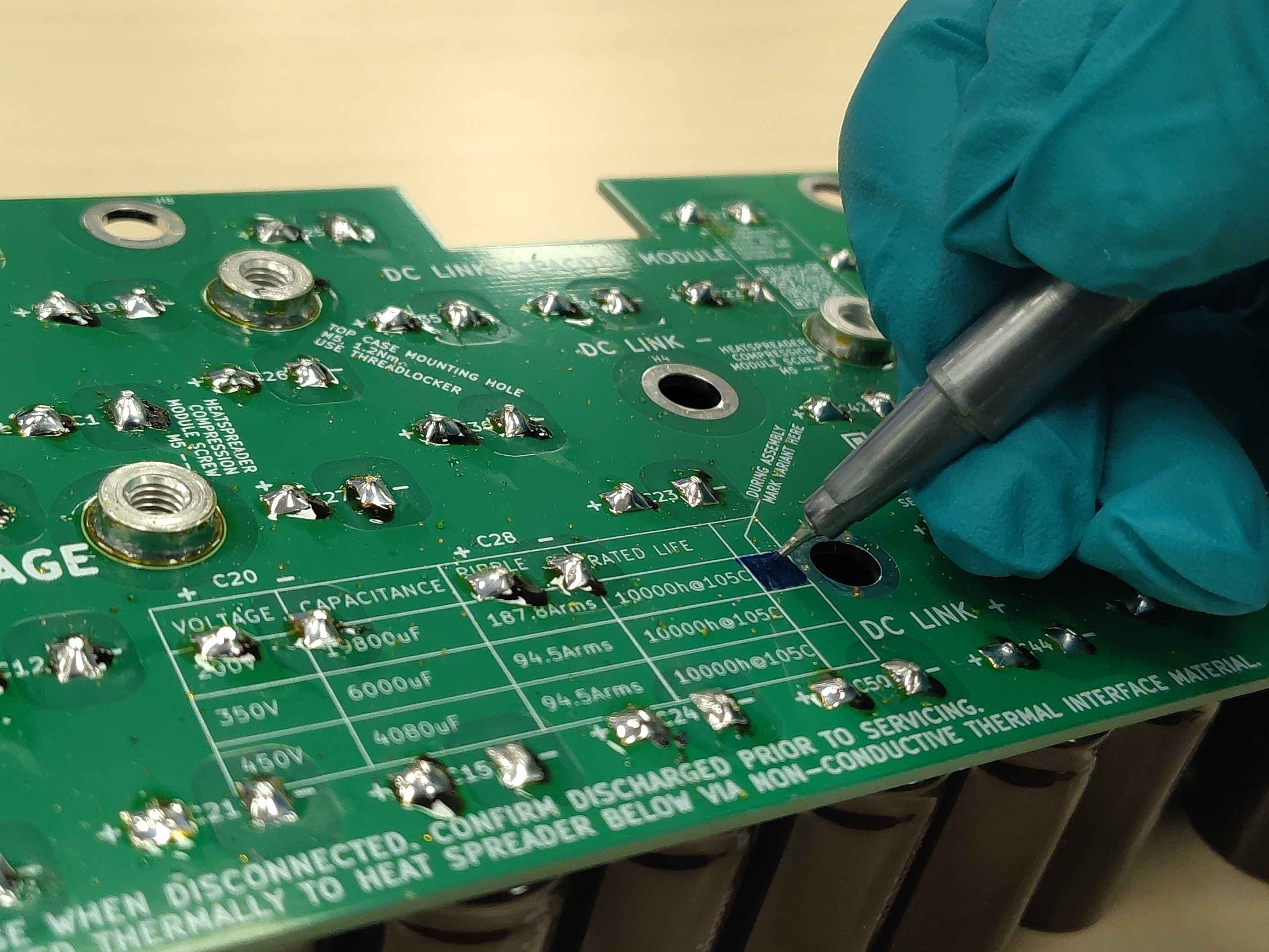
Near the end of assembly, locate the variant mark area on the PCB silkscreen and fill it in with the permanent marker. This identifies the assembled variant for traceability and future inspection.
Step 10 - Remove the pre-applied tape
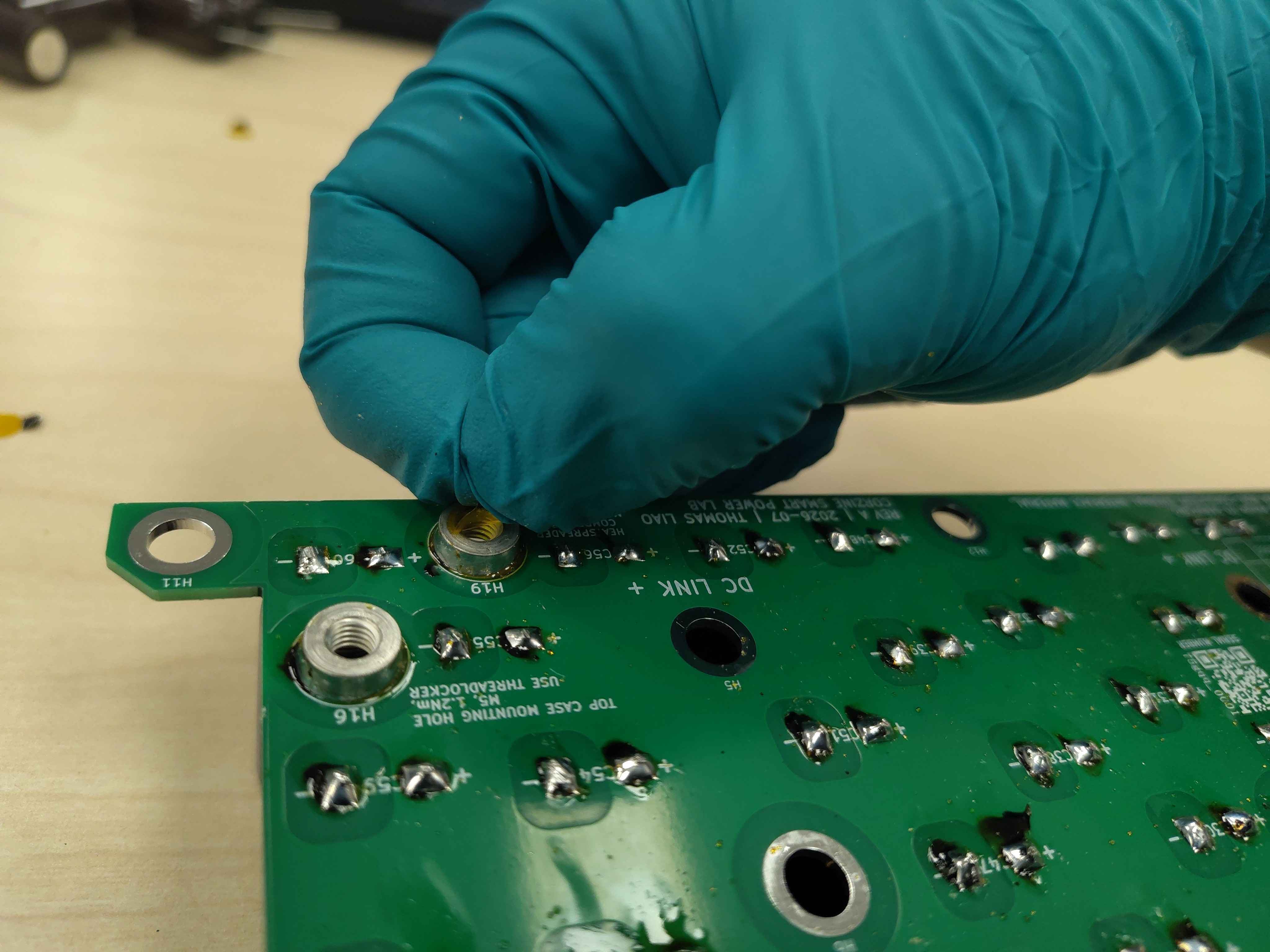
Carefully peel the protective tape off each standoff. Inspect the standoff solder joints one last time to make sure none were disturbed during cleaning or handling.
Final assembly
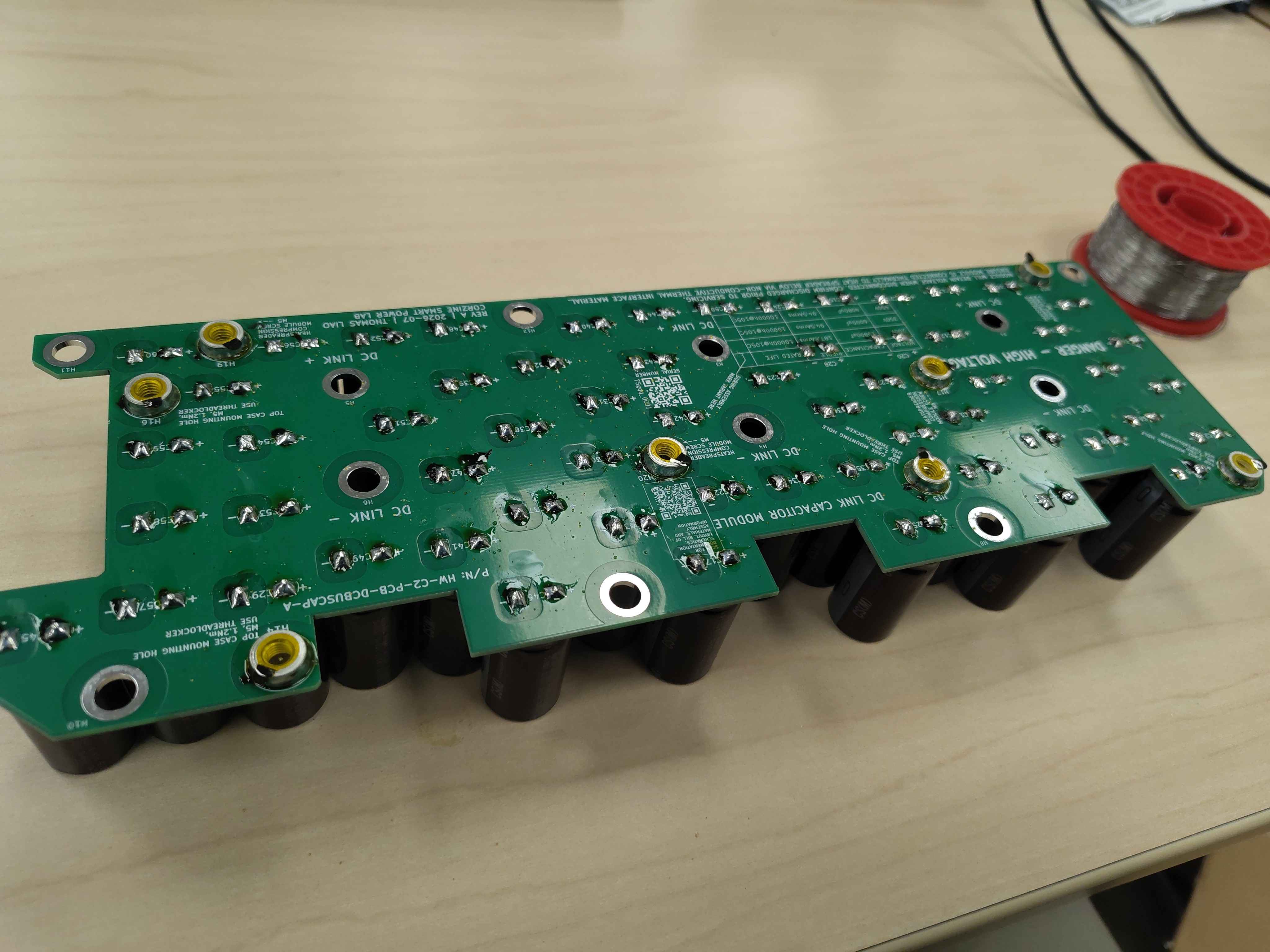
The finished DC-link capacitor board should have all 60 capacitors seated flush, both leads soldered and reflowed after trimming, flux residue cleaned, the variant mark applied, and all standoffs soldered in place with their protective tape removed.
Next steps
Set the assembled board aside and proceed with the remaining DC-link module assembly steps. The board will be mounted into the chassis after the bus bars and film capacitors are installed; see the integration guide (OV-C2-IG-INDEX) for the full assembly sequence.