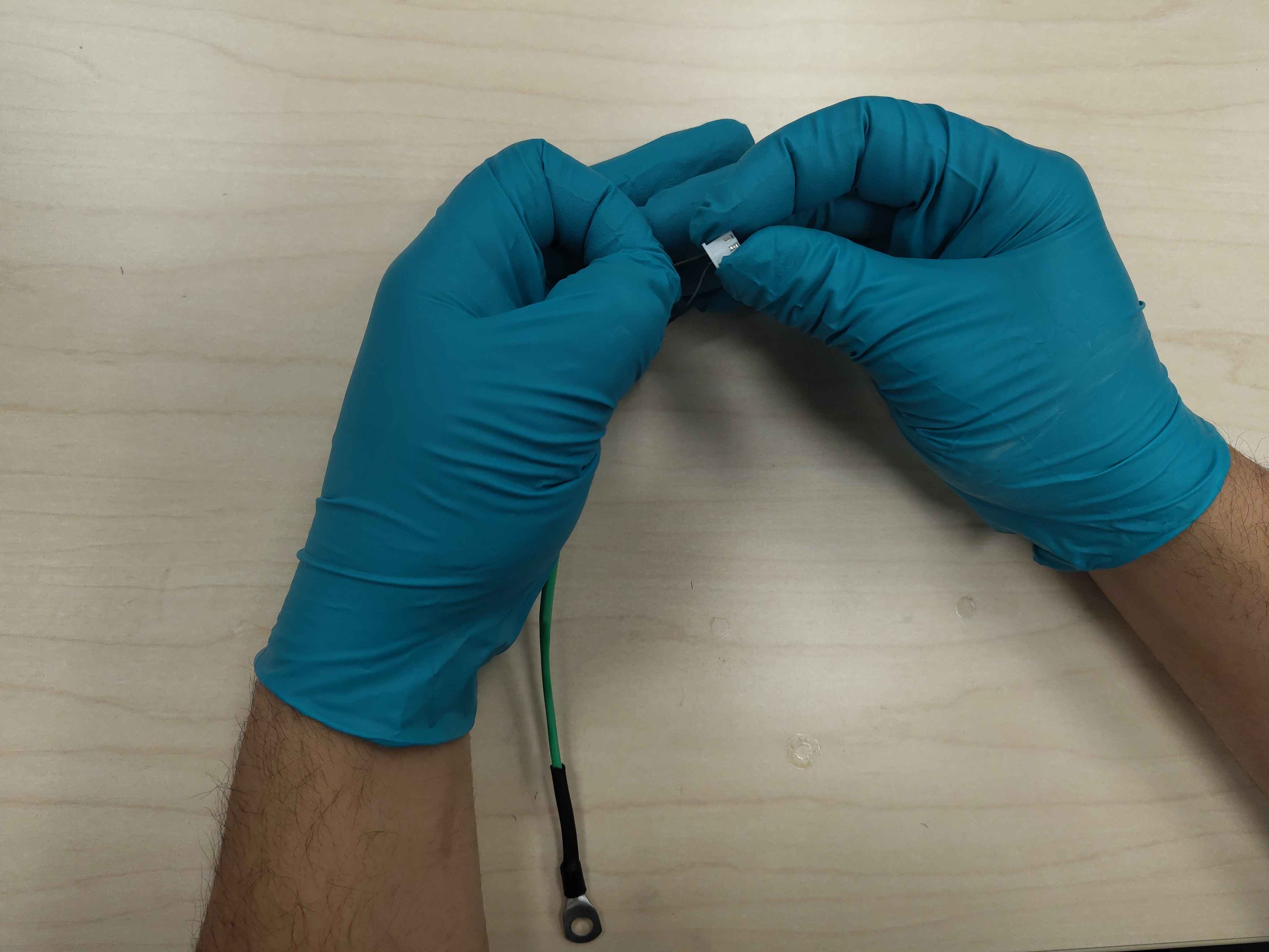
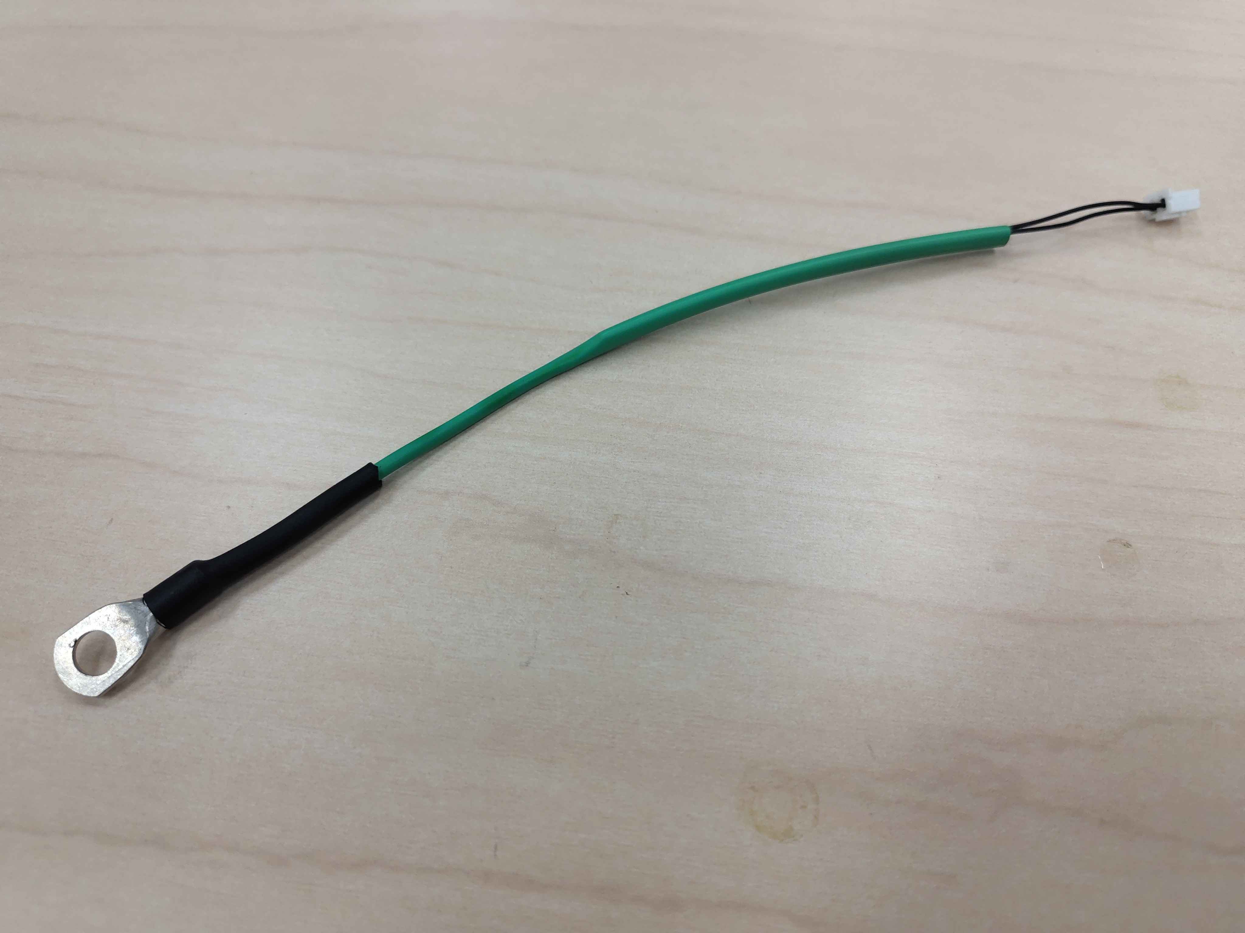
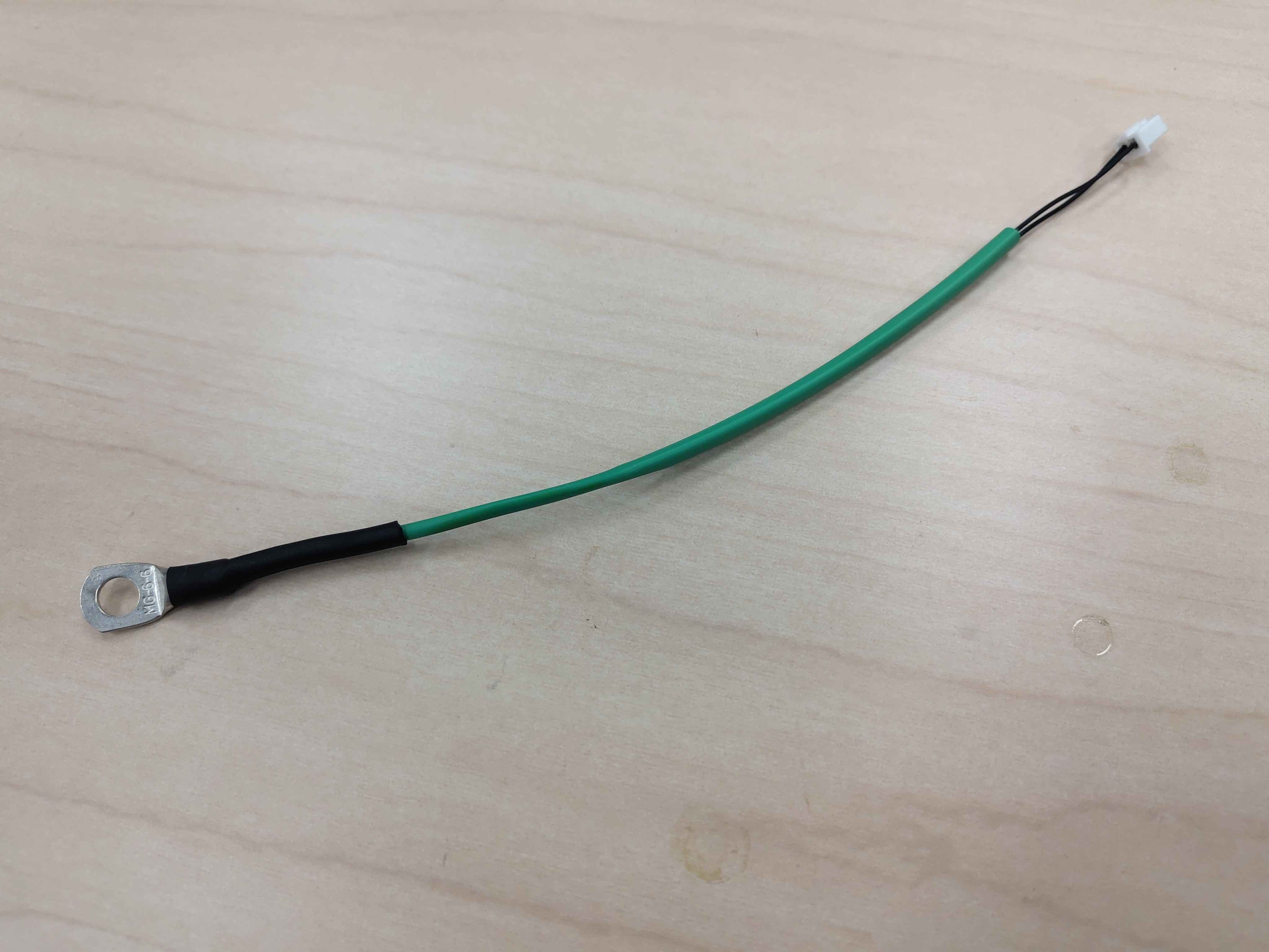
Build the IGBT temperature-sensor wiring harness for the Chassis Size 2 power stage.
Nav order
225
Normative refs
OV-C2-IG-INDEX
IGBT Temperature Sensor Wiring Harness
This guide covers building the small wiring harness that connects each IGBT module's temperature sensor to the control assembly. The harness has a ring-lug temperature sensor on one end and a two-position JST-style connector on the other.
Safety
- Do not power the inverter until all crimps, housings, and routing are verified.
- Keep the work area clean; stray wire strands or metal debris can short high-voltage bus bars.
Required materials and tools
Item
Qty
Notes
IGBT temperature sensor with pre-crimped ring lug
1
Per harness
2-position JST-style housing
1
Per harness
Crimp terminals for JST-style housing
2
Per harness
Heat-shrink tubing, 1/8 in (3 mm)
6 in / 150 mm
Insulates leads from high-voltage bus bars
Heat-shrink tubing, 1/4 in (6 mm)
~2 in / 50 mm
Strain relief at ring-lug base
Wire stripper
1
Precise, for 28 AWG or similar fine wire
Crimping tool
1
Sized for the JST-style terminals used. The IWS-3220M (or equivalent micro-connector crimper) is recommended
Heat gun
1
For shrinking tubing
Flush cutters
1
For trimming wire and heat-shrink
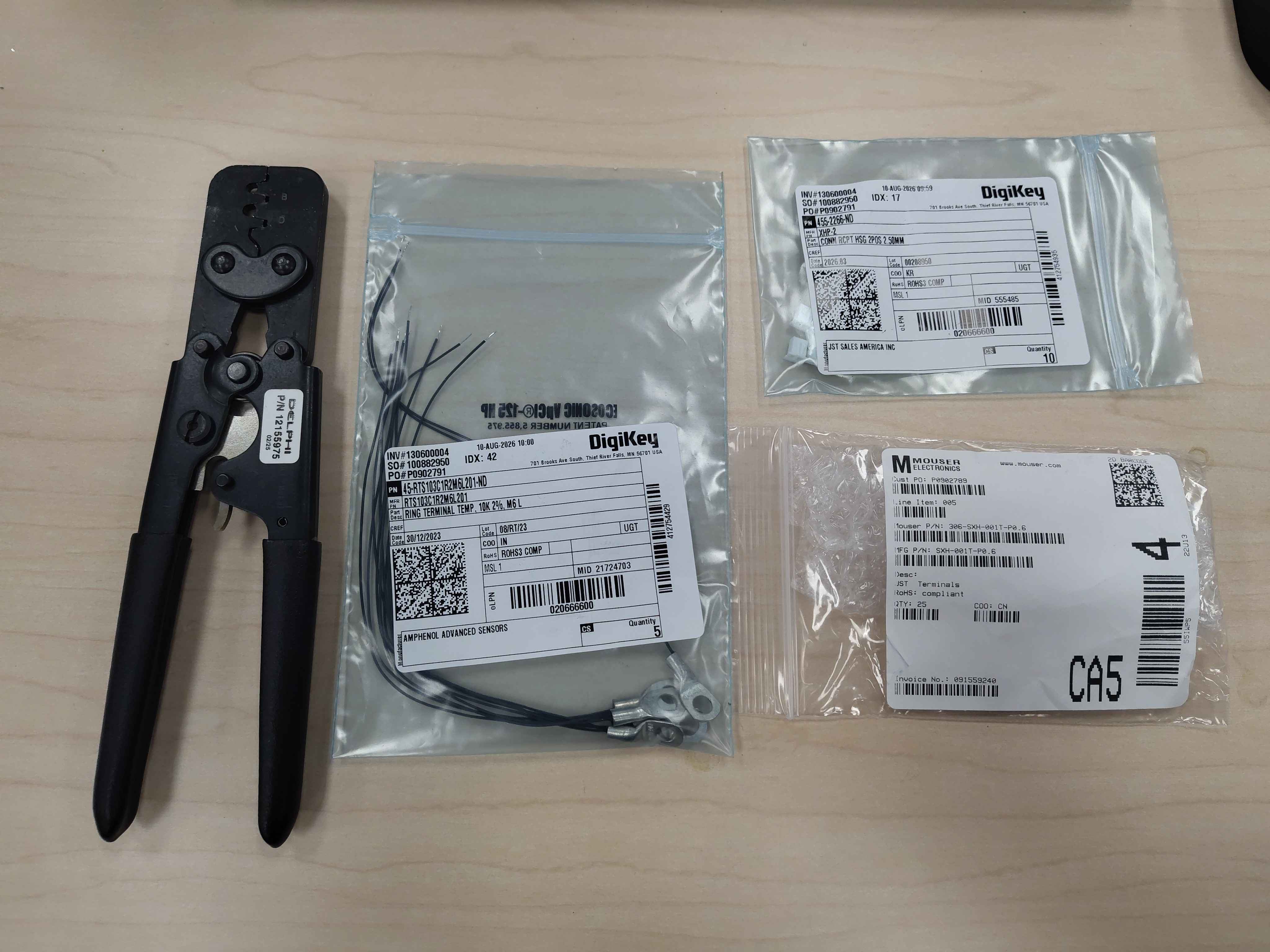
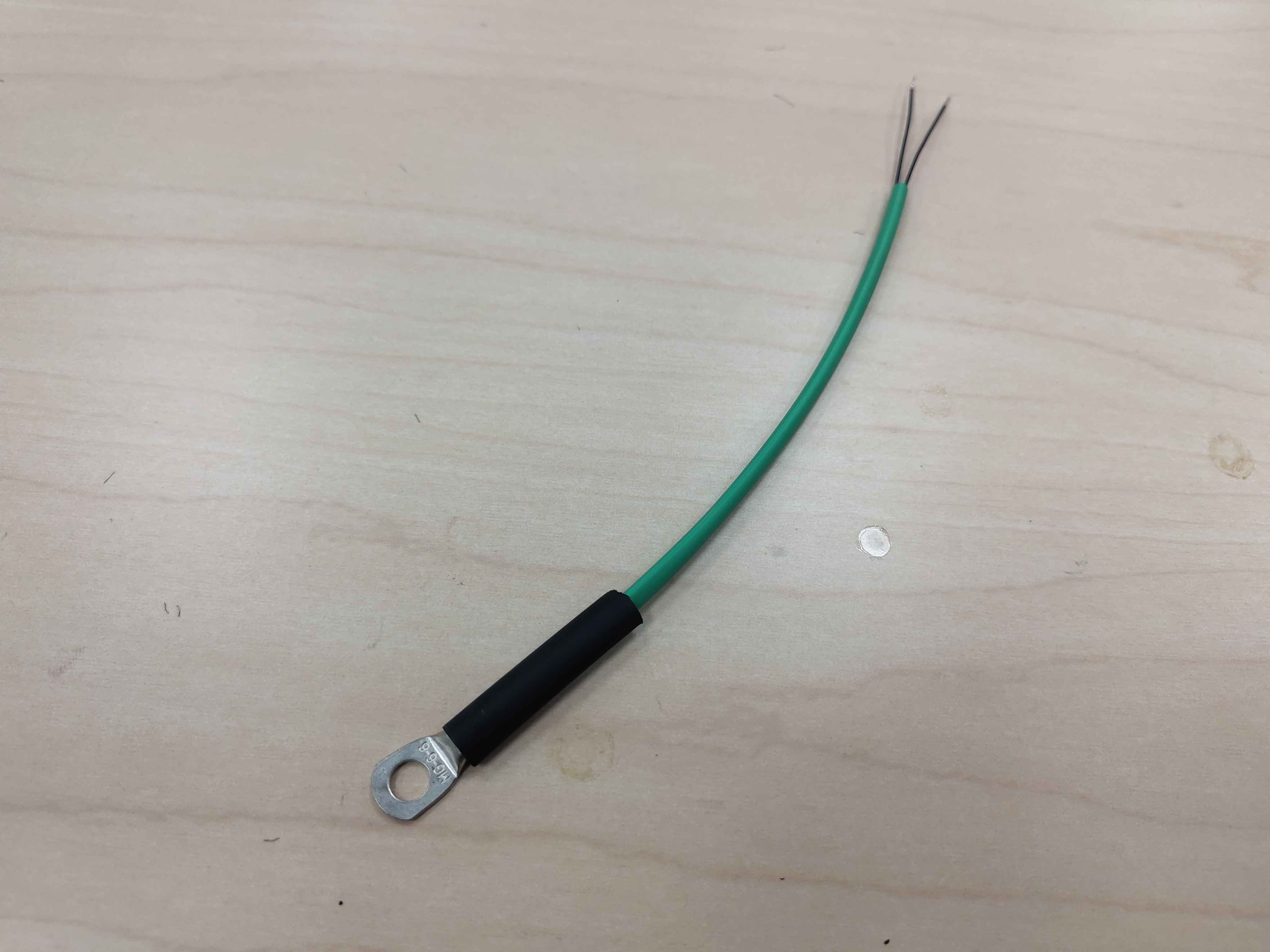
Parts laid out for the temperature-sensor harness
Step 1 - Slide the heat-shrink onto the harness
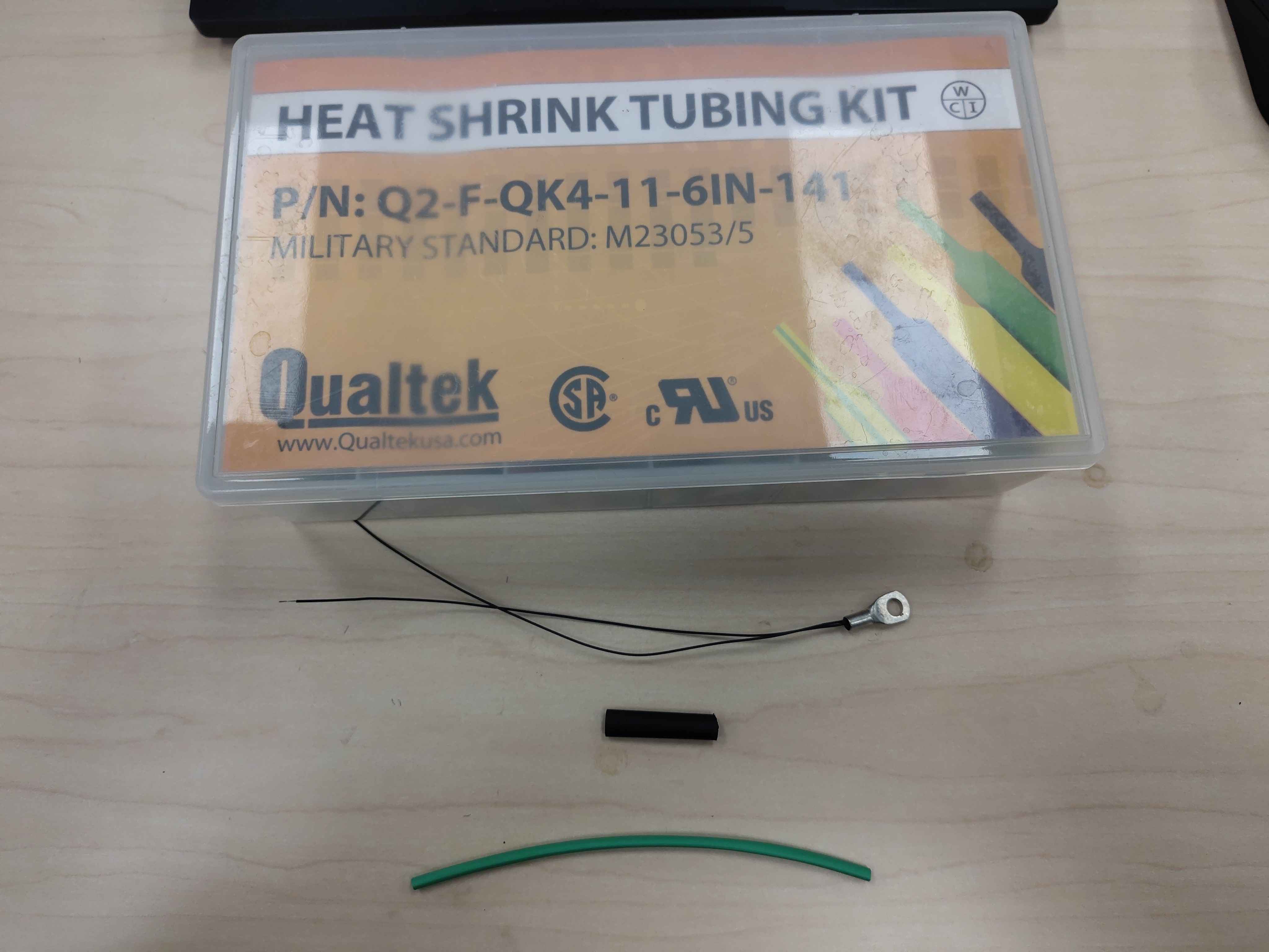
Slide both pieces of heat-shrink tubing onto the sensor lead before doing anything else. Once the JST terminals are crimped, the heat-shrink cannot pass over them.
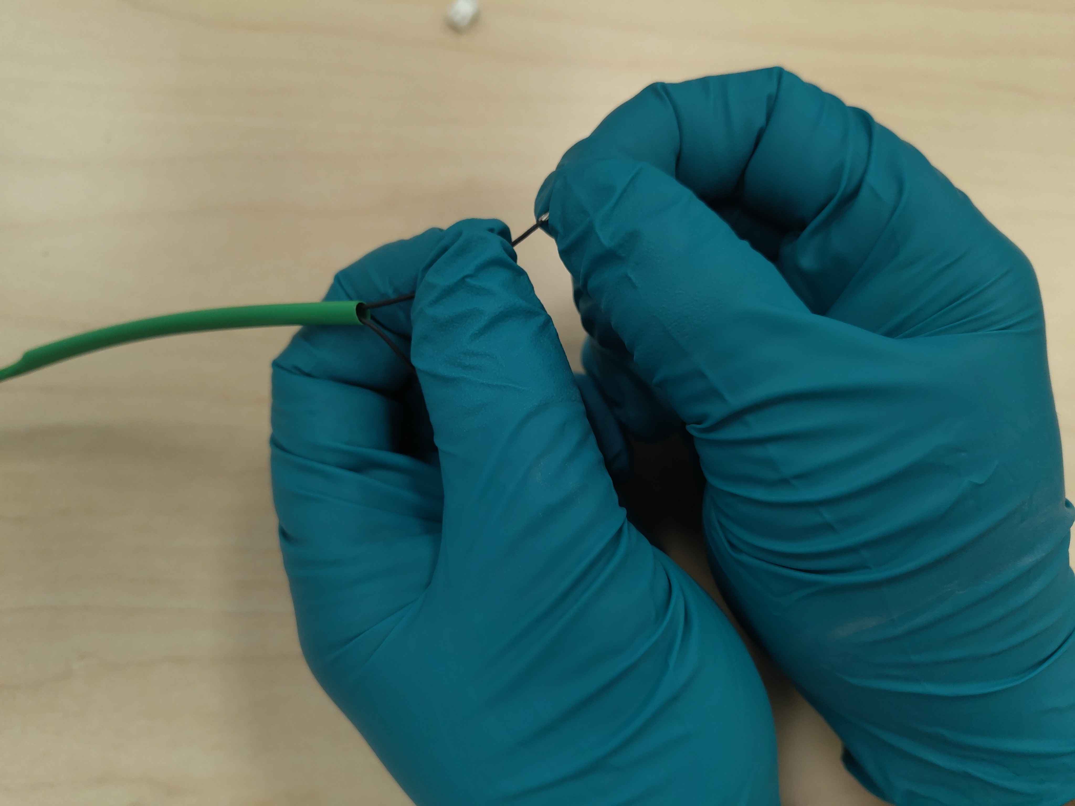
First, slide the 6 in (150 mm) piece of 1/8 in heat-shrink over the entire lead. This will later insulate the lead from nearby high-voltage bus bars.
Next, slide the ~2 in (50 mm) piece of 1/4 in heat-shrink over the lead and up against the ring-lug base. This will form strain relief at the lug.
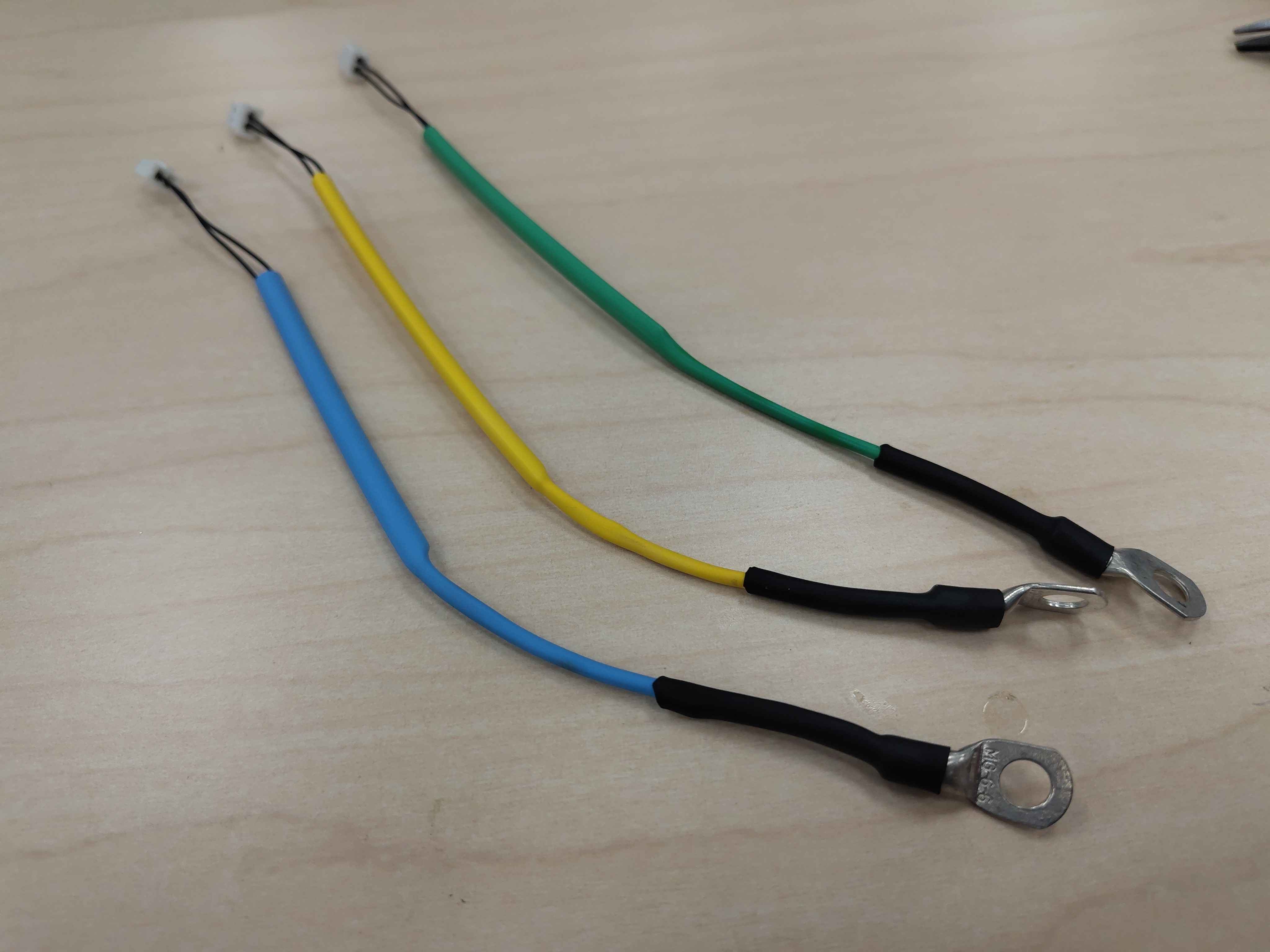
Tip: It is recommended to build a harness for all three phases. Use colored heat-shrink to identify them: yellow for phase U, green for phase V, and blue for phase W. This makes it much easier to keep the sensors straight during final routing and connection.
Three finished harnesses with yellow, green, and blue heat-shrink for phases U, V, and W
Heat-shrink pieces ready to be slid onto the sensor leadThe long 1/8 in heat-shrink slid over the sensor leadThe 1/4 in heat-shrink slid over the ring-lug base
Step 2 - Shrink the tubing
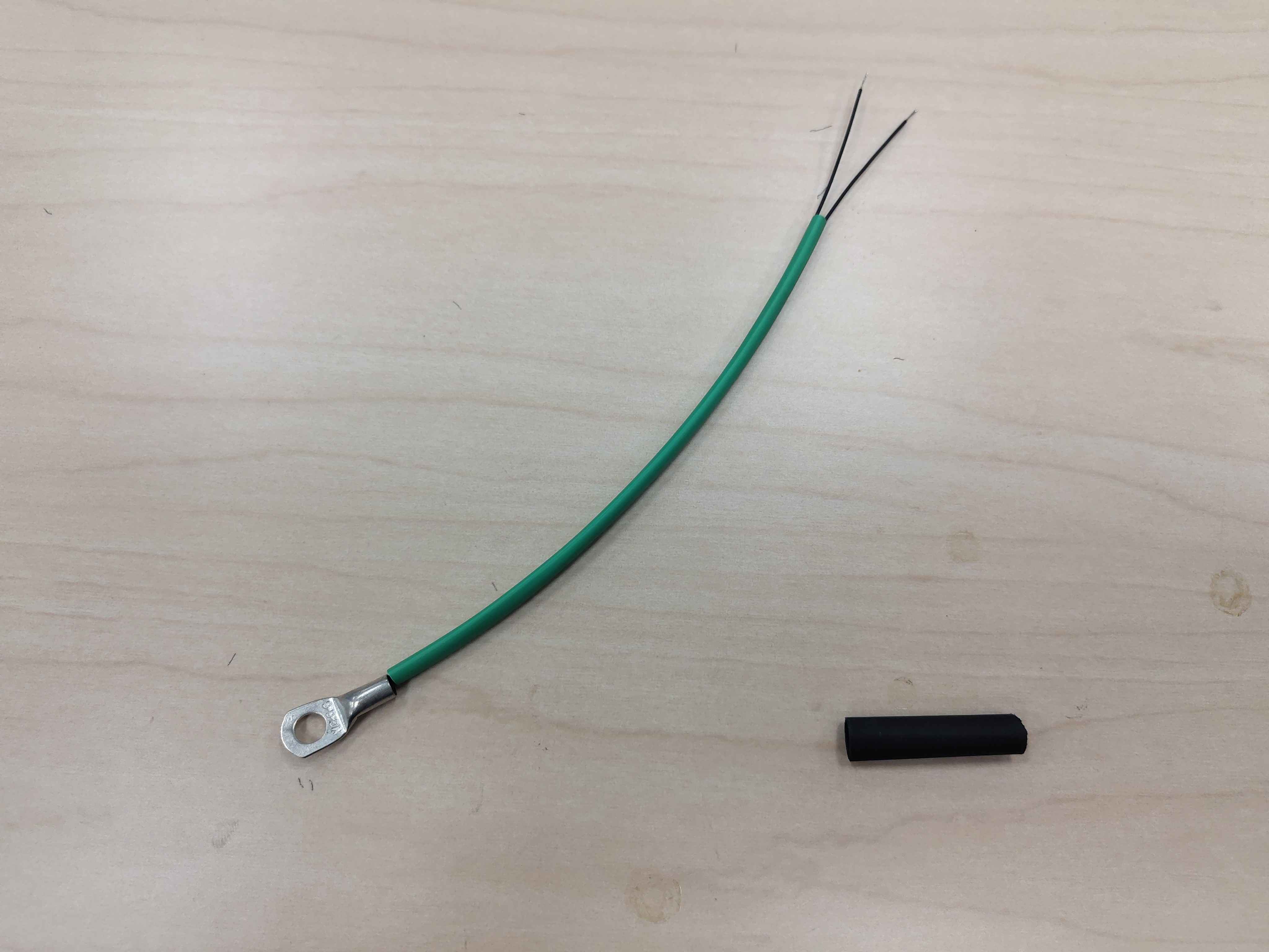
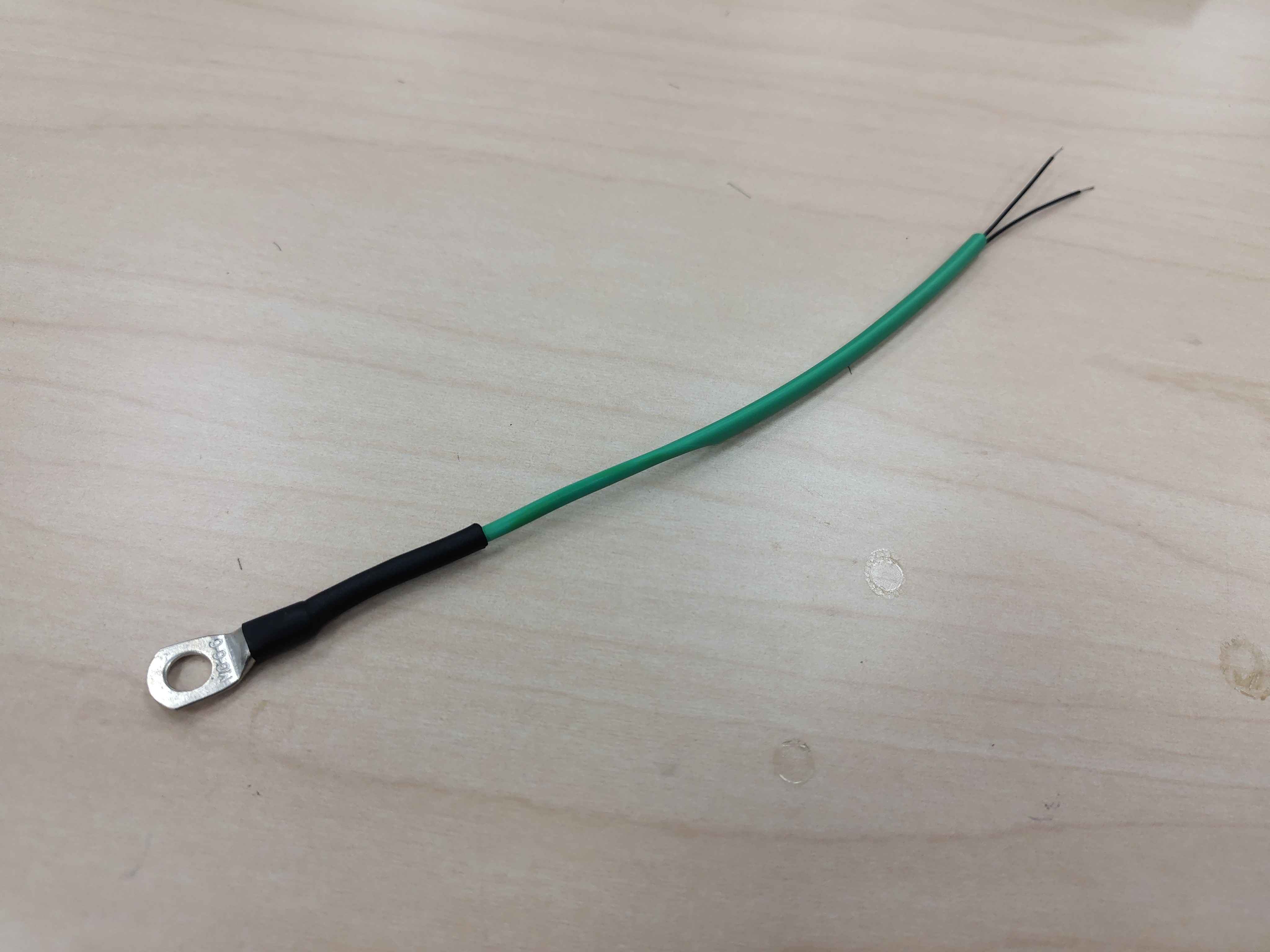
Use a heat gun to shrink both pieces of tubing. Shrink only about the first 3 in (75 mm) of the long 1/8 in piece from the ring-lug end, leaving the rest unshrunk so the harness stays flexible where it plugs into the control board. Shrink the 1/4 in piece fully around the base of the ring lug for strain relief.
Heat-shrink partially shrunk near the ring lug, leaving the rest flexible
Step 3 - Prepare the wire ends for crimping
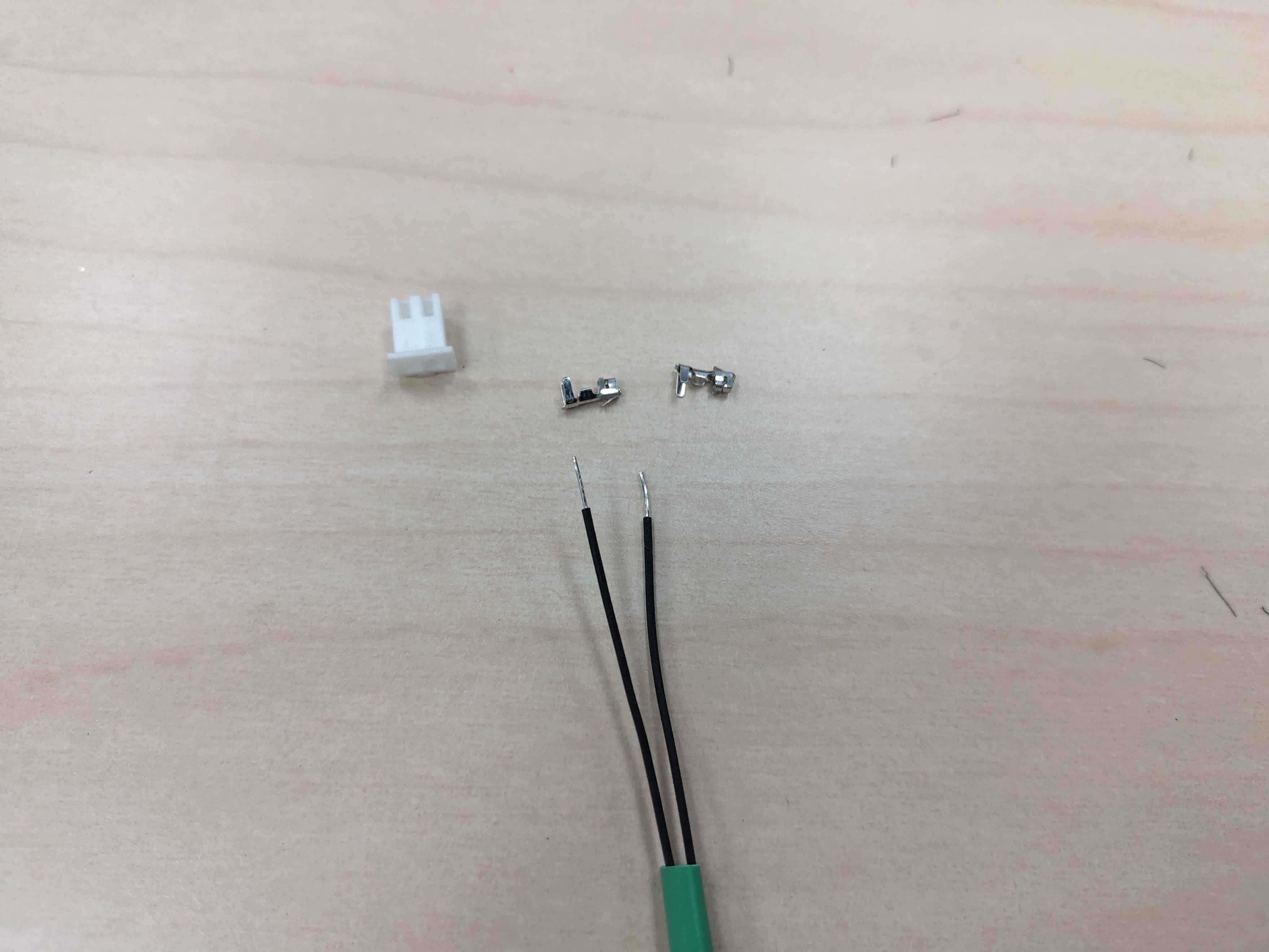
Strip approximately 1.5 mm to 2.0 mm of insulation from each of the two fine sensor wires. If the exposed copper is too long it will extend past the terminal barrel and prevent the connector from mating; if too short the front wings will bite insulation instead of copper and the joint will fail.
Stripped wire ends, terminals, and housing laid out for crimping
Step 4 - Crimp the terminals
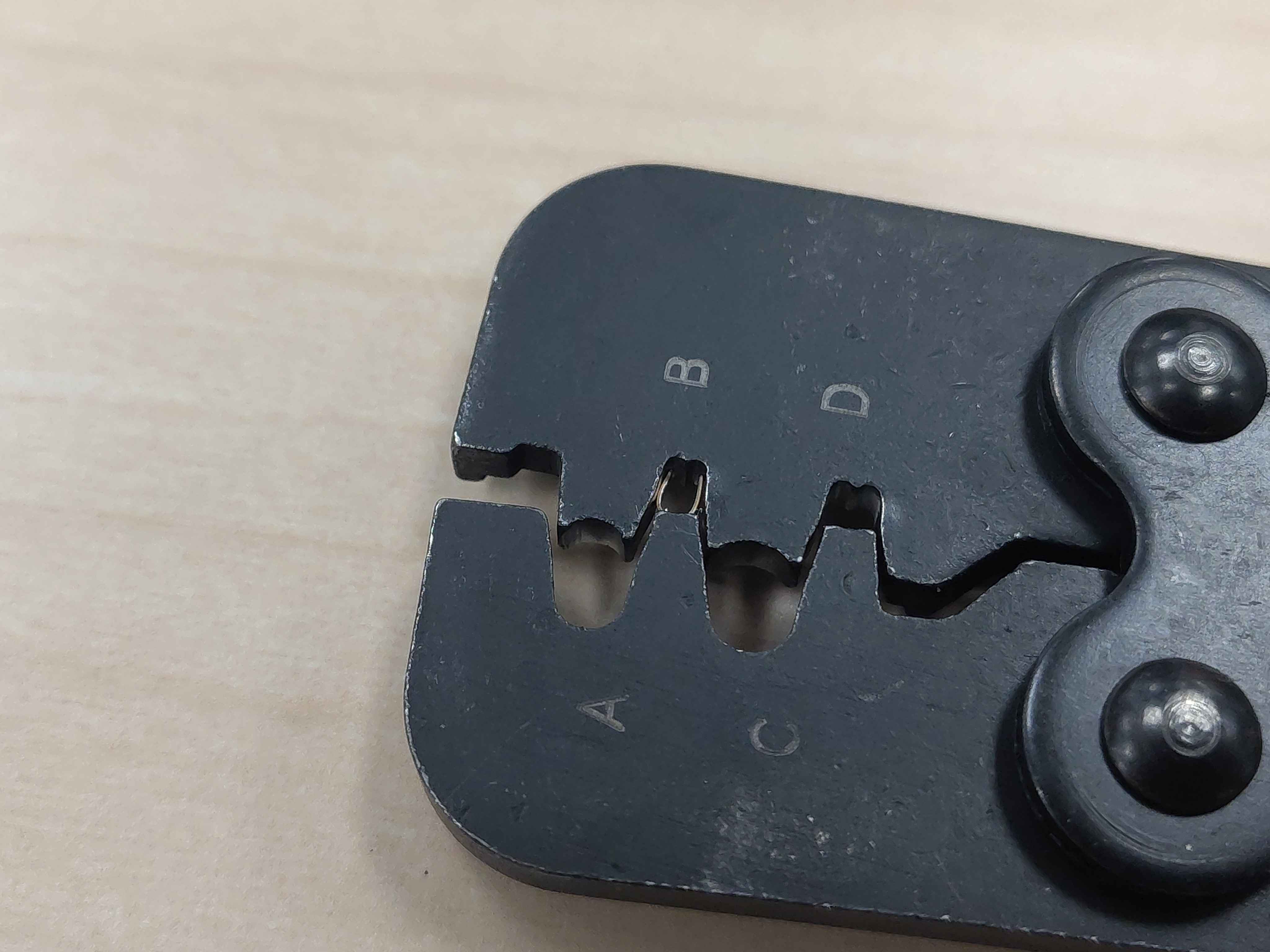
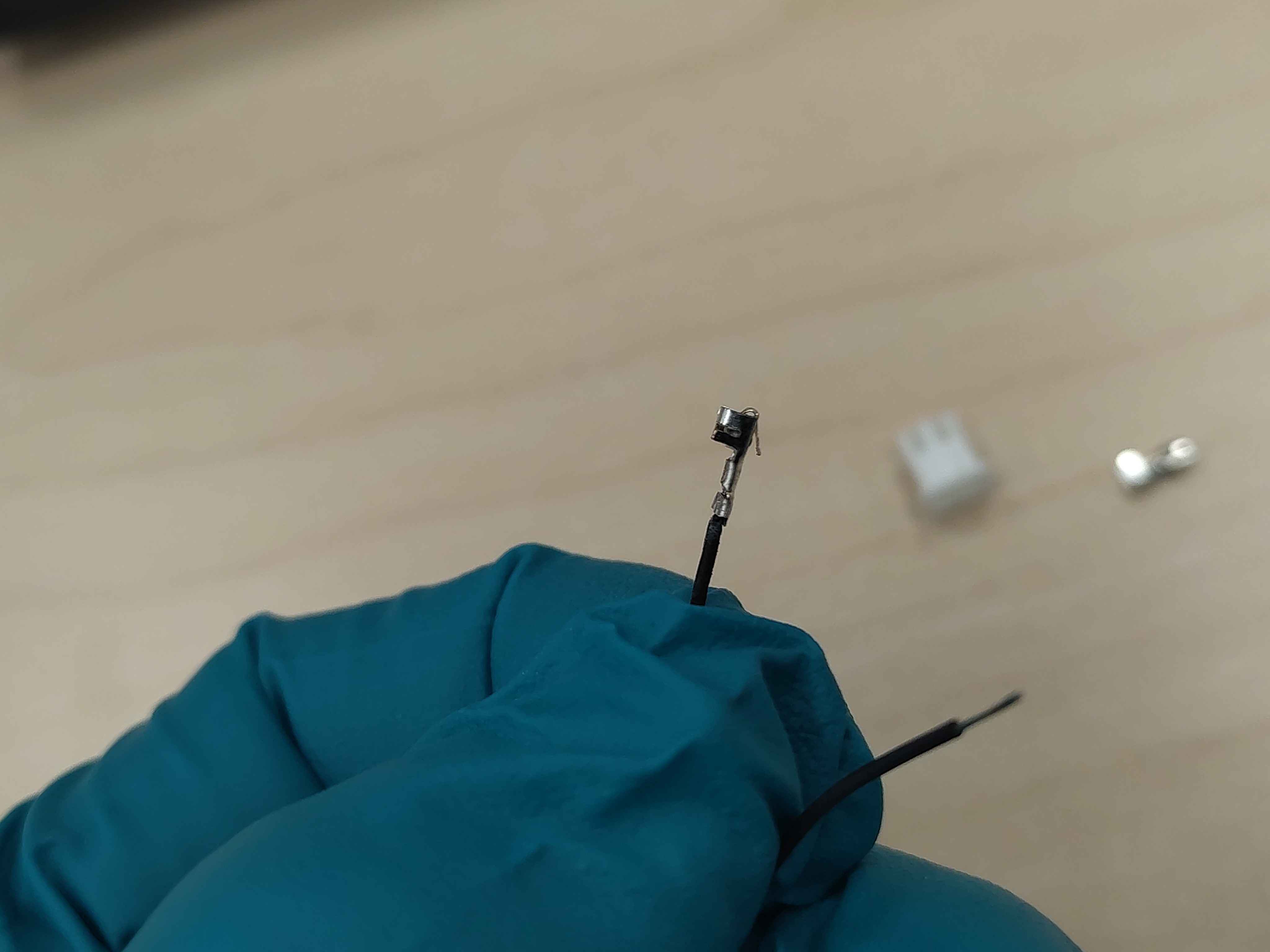
Place one terminal into the correct die of the crimping tool. Insert a stripped wire so the front set of wings clamps strictly onto the bare copper (conductor crimp) and the rear set of wings clamps strictly onto the plastic jacket (insulation/strain-relief crimp). Squeeze firmly to complete the crimp.
Errata: The crimping tool shown in the photo below is not the recommended IWS-3220M. Use the tool called out in the materials list (IWS-3220M or an equivalent micro-connector crimper sized for these terminals) rather than matching the photo.
Do not:
- Tin the wire with solder before or after crimping. Solder prevents the gas-tight cold weld and creates a brittle stress point.
- Fold the strands back to thicken the wire. This creates an uneven mass that cannot be compressed uniformly.
Tip: Be careful not to flatten or deform the small locking tang on the back of the terminal. If it is damaged, the terminal will not lock into the housing.
Terminal positioned in the crimping toolA completed crimp on the sensor wire
Step 5 - Pull-test each crimp
Grip the wire and the terminal and pull firmly. A good crimp on 28 AWG wire should withstand at least 5 N (roughly 1.1 lb). If the insulation stretches and the bare copper slides out of the crimp, the conductor crimp has failed — cut it off and redo it.
Performing a pull test on a freshly crimped terminal
Step 6 - Insert the terminals into the housing
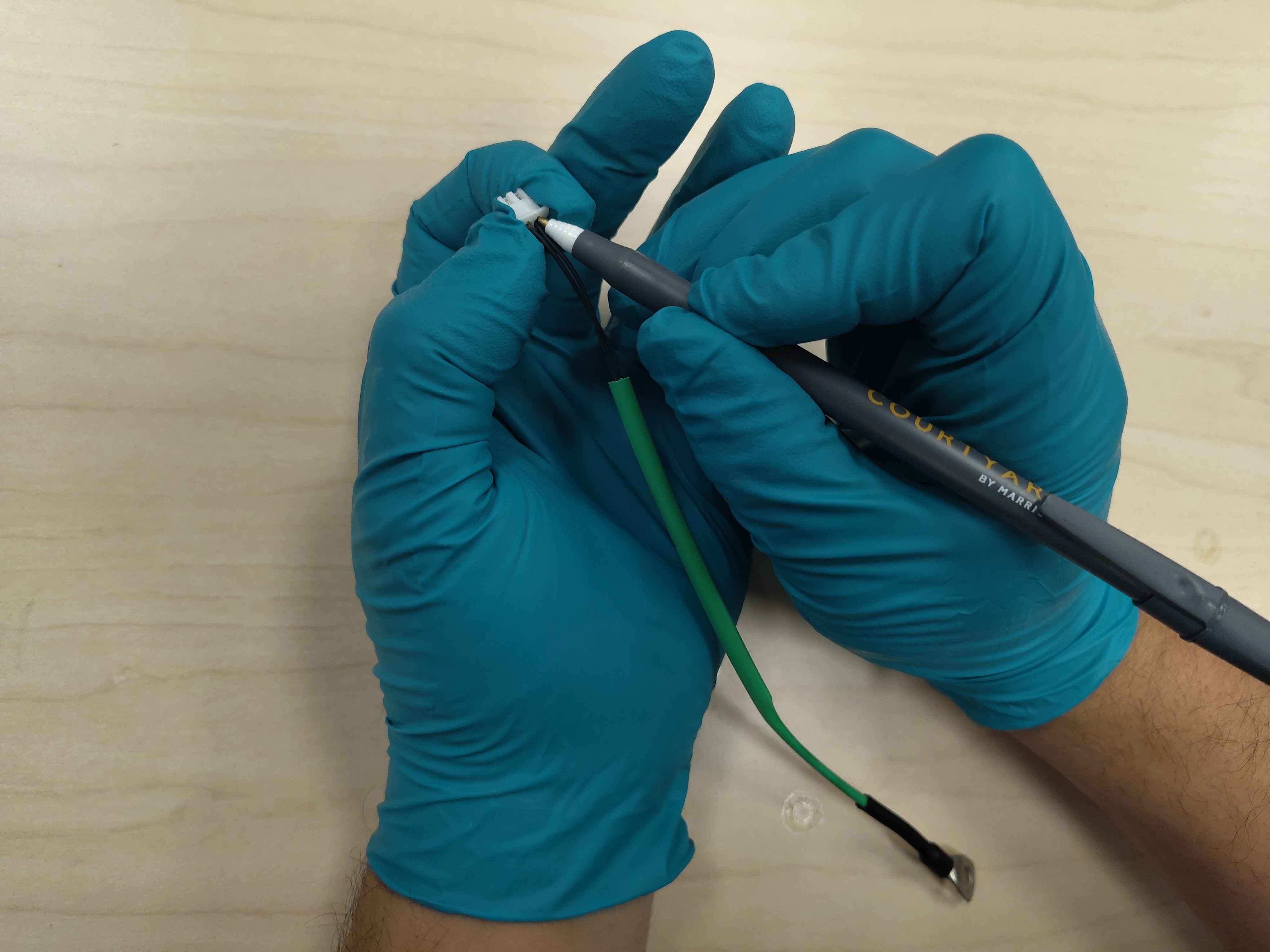
Push each crimped terminal into a cavity of the 2-position housing until you feel and hear a distinct click. The temperature sensor is non-polarized, so either wire can go into either cavity.
Tip: If a terminal does not want to seat fully, the tip of a ballpoint pen can be used to push it in the last little bit without damaging the locking tang.
Inserting a crimped terminal into the housingTerminal fully seated in the housing
Step 7 - Verify the housing retention
After both terminals are inserted, gently pull on each wire to confirm the locking tang has engaged and neither terminal can back out of the housing.
Pull-testing the wires after insertion to verify the locking tang
Final assembly
The finished harness should have:
The ring-lug temperature sensor end with shrunk strain-relief tubing at the lug base.
The long 1/8 in heat-shrink only partially shrunk near the lug end, leaving the remainder flexible.
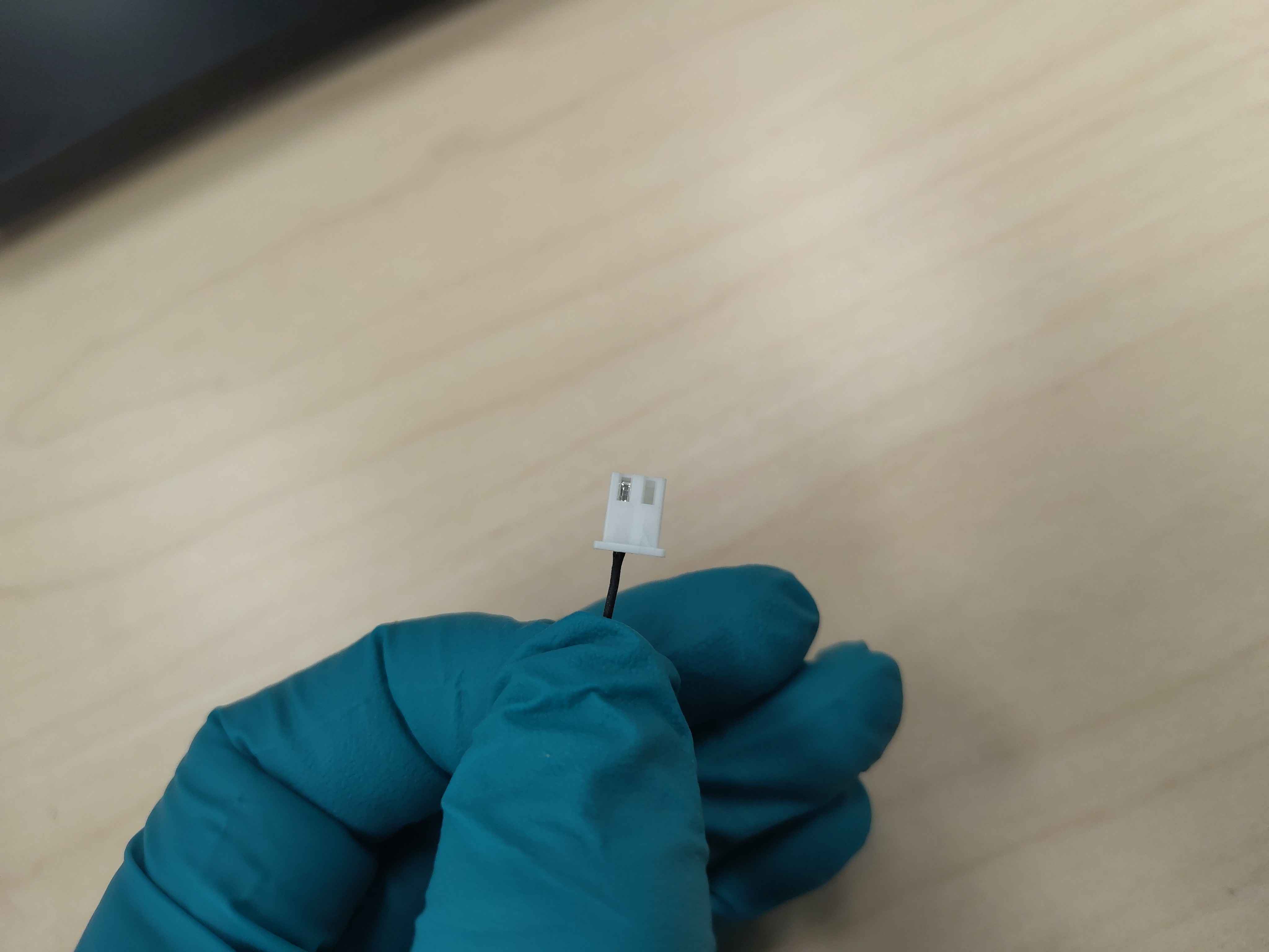
Two properly crimped and pull-tested terminals locked into the 2-position housing.
Completed temperature-sensor harnessCompleted harness shown from another angle
Next steps
Repeat this process for each IGBT temperature sensor required by the build. Even if the current control module only has inputs for two of the three heatspreader sensors, it is recommended to build and install the third harness anyway and leave it unconnected. Having the spare sensor in place makes it easy to swap over if one of the active sensors fails later.
Once all harnesses are built, route and connect them during the IGBT module installation and control-assembly wiring steps described in the integration guide (OV-C2-IG-INDEX).